MOIRCS Filters
Broadband Filters
The following table lists the broadband filters currently installed in MOIRCS, along with their estimated sensitivities.
Our broadband filters are designed to follow the MKO filter system (Tokunaga, Simons, and Vacca 2002, PASP, 114, 180; Warren & Hewett 2002, ASP Conf, Vol 283, 369). The transmission curves for each filter are sourced from the suppliers' datasheets.
Estimated sensitivities are for a 5 sigma detection in 1 hour of integration, assuming good (0.5'') seeing and moderate sky conditions (equivalent to the sky background flux of the Subaru ETC; see also the Exposures page). Point source S/N is measured in a 1.5''-diameter aperture, assuming all light from the source is contained within it. Extended source sensitivities are given in mag per arcsec2. All the magnitudes are in AB units.
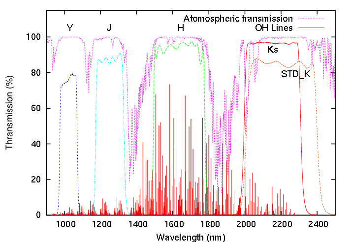
Broad-Band Filters Specification
| Filter*1 | Wavelength [um] | Sensitivity (AB mag)*2 | Magnitudes*3 for 1 e-/s [1 ADU/s] for ch1/2 |
||||
|---|---|---|---|---|---|---|---|
| Name | Plot | List | Centre | Width | [mag] | [mag/arcsec] | |
| Y | 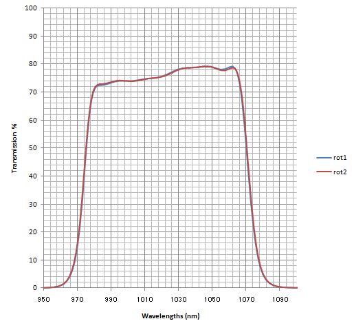 |
 |
1.02 | 0.10 | 24.49 | 25.79 | 27.47/27.28 [26.68/26.53] |
| J | 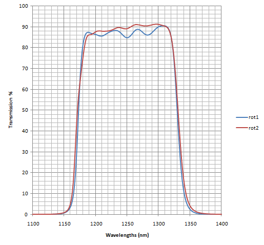 |
|
1.26 | 0.17 | 24.05 | 24.35 | 27.79/27.74 [27.0/26.99] |
| H | 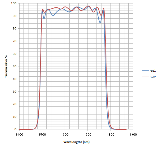 |
|
1.64 | 0.28 | 23.81 | 24.11 | 28.24/28.27 [27.45/27.53] |
| Ks | 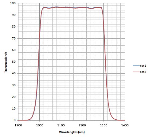 |
|
2.15 | 0.31 | 23.84 | 24.14 | 27.98/28.06 [27.19/27.31] |
| (STD_K)*4 | 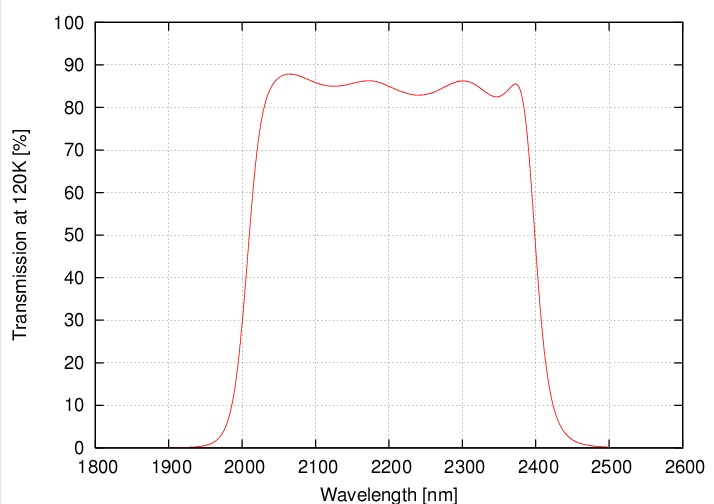 |
|
2.20 | 0.40 | --- | --- | --- |
Notes:
*1: All of our standard YJHKs filters were replaced with "fringe-free" type (using wedged substrates) in August 2009. The Ks filter was replaced in July 2008; it is the same one used as "Ks_wedge" during S08A for testing. The J & H filters were replaced in July 2009. The transmission curves are approximately similar to the old ones, but with slightly higher throughput.
*2: For conversion from Vega to AB magnitude, we use Y_AB=Y_vega+0.64, J_AB=J_vega+0.94, H_AB=H_vega+1.38, Ks_AB=Ks_vega+1.86 (Tokunaga & Vacca 2005)
*3: The magnitude zero points shown here are from a single observation executed on May 19, 2016.
*4: Currently unavailable. Users who wish to use the STD_K filter should contact the SA at least 1 year before the submission of the proposal.
Medium-Band Filters
A complete suite of 8 medium-band filters are available from S27A. The new MBJ1, MBH1, & MBK1 medium-band filters, as well as MBJ2, MBH2, & MBK2*Note 1,2, are introduced as a carry-in filter by the team led by Dr. Yusei Koyama. They are happy to allow these filters for use if there is no scientific conflict. Those who want to use the filter should first contact Dr. Koyama (email to: koyama(at)naoj.org: change (at) to @) for permission.
Note 1:
These filters are actually single filter (see a report on J2H2K2 filter) with three filter windows in it (J1H1K1 and J2H2K2). We select one window using another filter (J, H, Ks). Due to the situation, the filter function of these new medium-band filters are affected by the shape of the transmission curve of these broadband filters.
Note 2:
As of writing, the J1H1K1 filter is not installed yet. Thus, performance evaluation is not started yet. We will try to update it soon before the start of S27A. Due to the situation, the use of these filters are under the shared-risk policy.
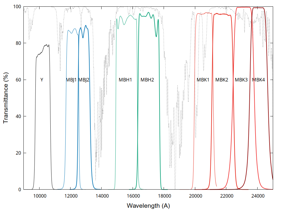
The estimated sensitivities listed are for a 5 sigma detection in 1-hour integration, assuming a good seeing & dark sky condition(Note 2). The S/N is measured in a 1.5''-diameter aperture where we assume all the light from the source is in it. Extended source sensitivities are in mag per arcsec2. These values are in AB magnitude system.
Medium-Band Filters Specification
| Filter | Wavelength [um] | Typical Sky Counts [ADU/s](Note 2) | Sensitivity (AB mag)(Note 3) | Magnitude Zero Points for ch1/2(Note 2) |
|||||
|---|---|---|---|---|---|---|---|---|---|
| Name | Plot | List | Centre | Width | Channel 1 | Channel 2 | [mag] | [mag/arcsec2] | |
| MBJ1(Note 4) |  |
|
1.185 | 0.078 | TBD | TBD | TBD | TBD | TBD |
| MBJ2(Note 4) | 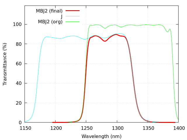 |
|
1.288 | 0.078 | 90 | 96 | 23.9 | 24.2 | 26.06/26.12 |
| MBH1 |  |
|
1.56 | 0.14 | TBD | TBD | TBD | TBD | TBD |
| MBH2 | 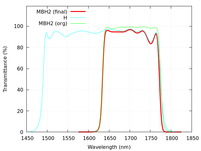 |
|
1.702 | 0.14 | 324 | 349 | 23.6 | 23.9 | 26.48/26.59 |
| MBK1(Note 5) |  |
|
2.045 | 0.14 | TBD | TBD | TBD | TBD | TBD |
| MBK2 | 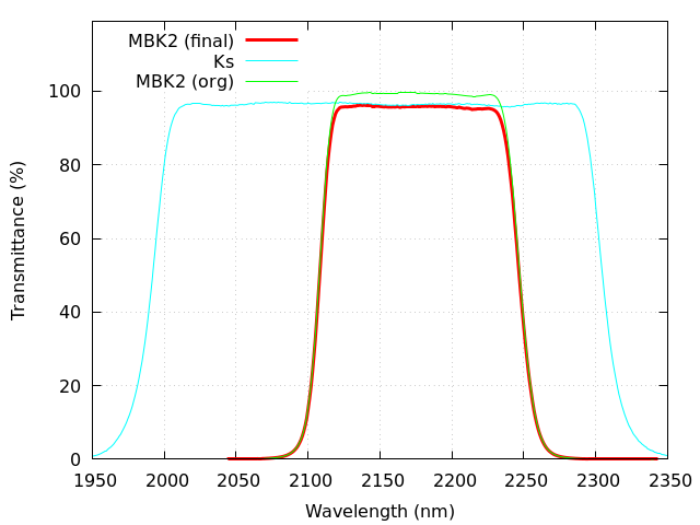 |
|
2.178 | 0.14 | 255 | 288 | 23.4 | 23.7 | 26.18/26.37 |
| MBK3(Note 1) | 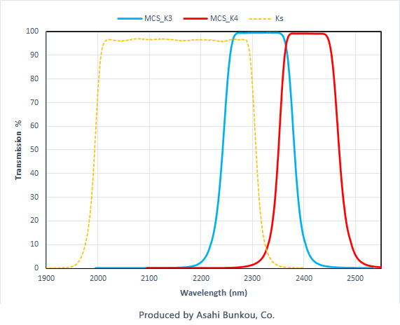 |
|
2.310 | 0.14 | 200 | 225 | 23.5 | 23.8 | 26.11/26.28 |
| MBK4(Note 1) | |
|
2.410 | 0.12 | 425 | 480 | 22.8 | 23.1 | 25.82/25.99 |
Notes:
-
They are originally the user (carry-in) filters. Please read the policy for use.
-
The sky level and sensitivity for MBK3 & MBK4 are based on the data taken in Feb-May 2023. The actual background level largely depends on the atmospheric condition, especially for K4. We observed ±30% (for K3) to 50% (for K4) variation from day to day basis. The values for MBJ2, MBH2, and MBK2 are based on the single night data on May 2025, but the sky level for the MBK2 is adjusted to be consistent with the values for MBK3 and MBK4 tablated here.
-
These values are for the channel 1. The actual 1 hr exposure data could be shallower due to some additional noise source such as the bias drift, variable sky fluctuation, the additional noise by the sky subtraction process.
-
We have a plan to add an option to widen the bandwidth of MBJ1/MBJ2 in the future by introducing a wide_J filter.
-
The users should be aware that the actual transmission curve of the MBK1 filter is strongly affected by the presence of the two deep CO2 absorption bands around 2 um and 2.07um. For accurate calibration, you need to do further convolution of the above function with the estimated atmospheric transmittance during the observation.
Ghost Issue:
There are some ghosts near a bright stars on the images taken by the MBJ2, MBH2, MBK2 filters. These ghosts move the same way as objects on the detector, so they will ramain on the combined image after the coadding. The same type of the ghosts are likely appear on the images by the MBJ1, MBH1, and MBK1 filters too (not tested yet at 26/8/3). Please pay attention to the existence of ghosts when there are very bright stars on your images. Please consult the SA for more information.
Narrow-Band Filters
The central wavelength (CW) and band width (BW: defined by FWHM) of filters listed below are mostly from the direct measurement as installed in MOIRCS. The measurement values show very good agreement with the company-provided datasheets. Peak transmittance are around 80 to 90%, except for H2 filters.
Narrow-Band Filters Specification
| Filter | Wavelength [um] | |||
|---|---|---|---|---|
| Name | Plot | List | Centre | Width |
| NB119(2)(4) | 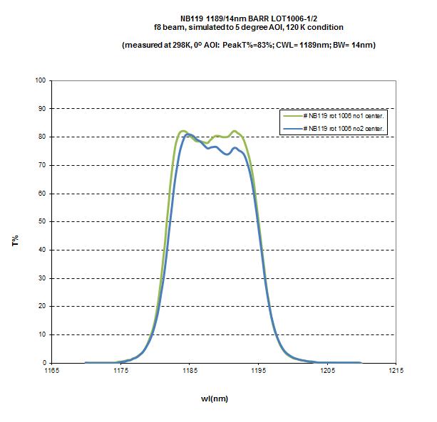 |
|
1.1885 (ch1) 1.1886 (ch2) | 0.0141 (ch1) 0.0135 (ch2) |
| NB1550(1) | 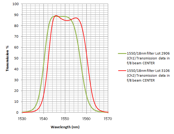 |
|
1.548 (ch1) 1.551 (ch2) | 0.018 (ch1) 0.019 (ch2) |
| NB1657(1) | 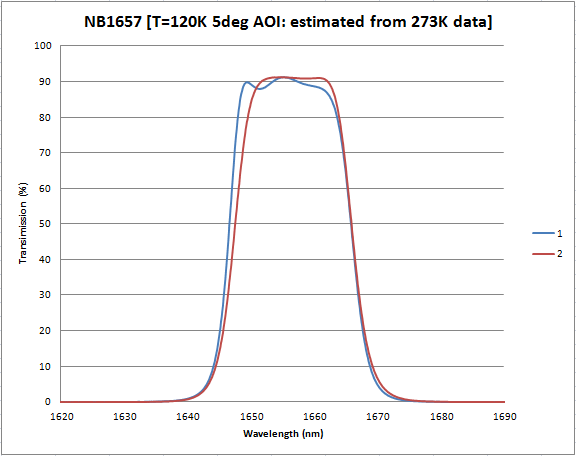 |
|
1.657 (ch1) 1.658 (ch2) | 0.020 (ch1) 0.019 (ch2) |
| [Fe II] | 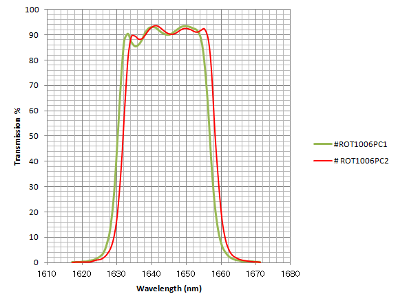 |
|
1.644 (ch1) 1.645 (ch2) | 0.027 |
| H2O_F3(6) | 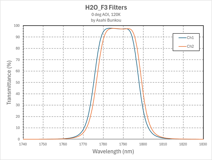 |
|
1.786 (ch1) 1.787 (ch2) | 0.023 |
| NB2071(1) | 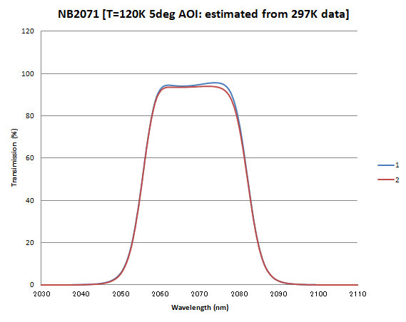 |
|
2.070 | 0.027 |
| NB2083(1) | 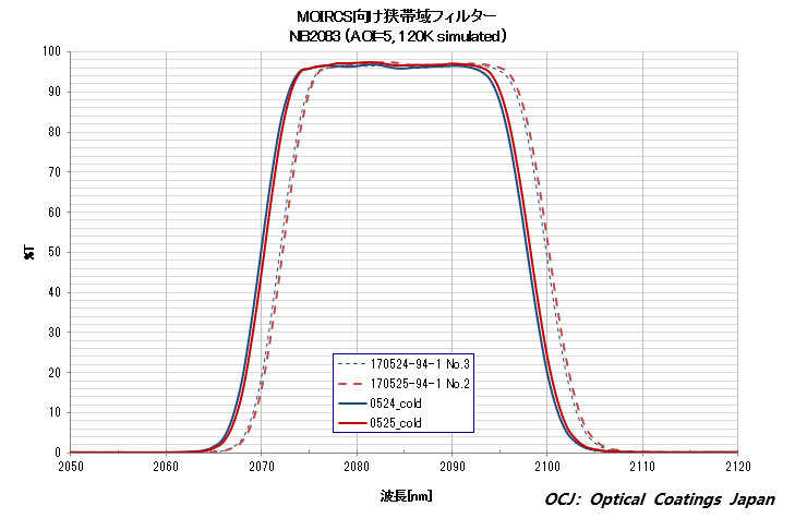 |
|
2.083 | 0.027 |
| NB2095(1) | 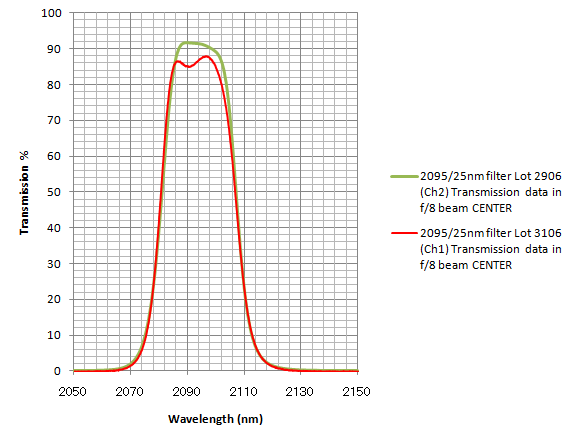 |
|
2.093 | 0.026 |
| H2v=1-0(3) | 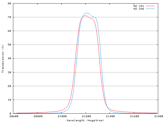 |
|
2.122 (ch1) 2.123 (ch2) | 0.021 |
| BrG | 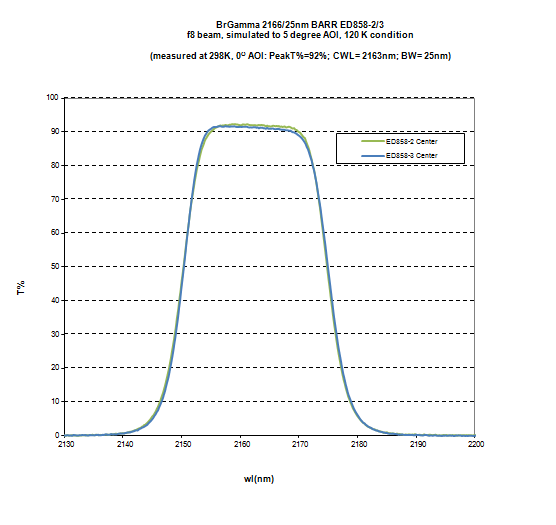 |
|
2.165 | 0.025 |
| BrG_ON(1)(5) | 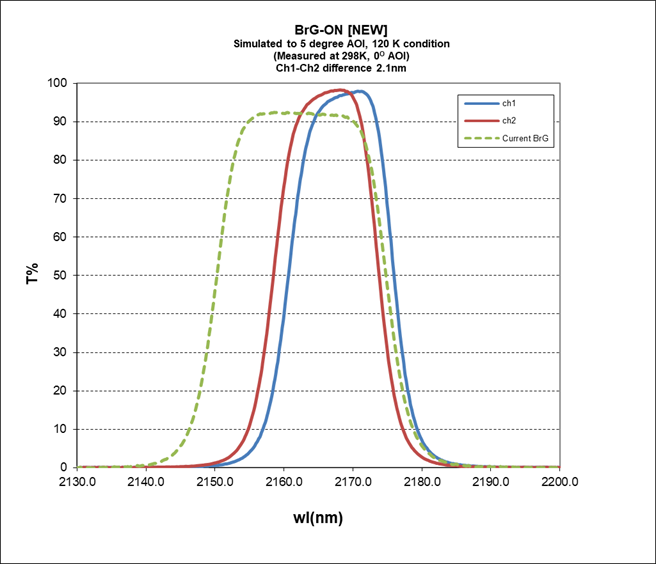 |
|
2.168 (ch1) 2.166 (ch2) | 0.0155 |
| BrG_OFF(1)(5) | 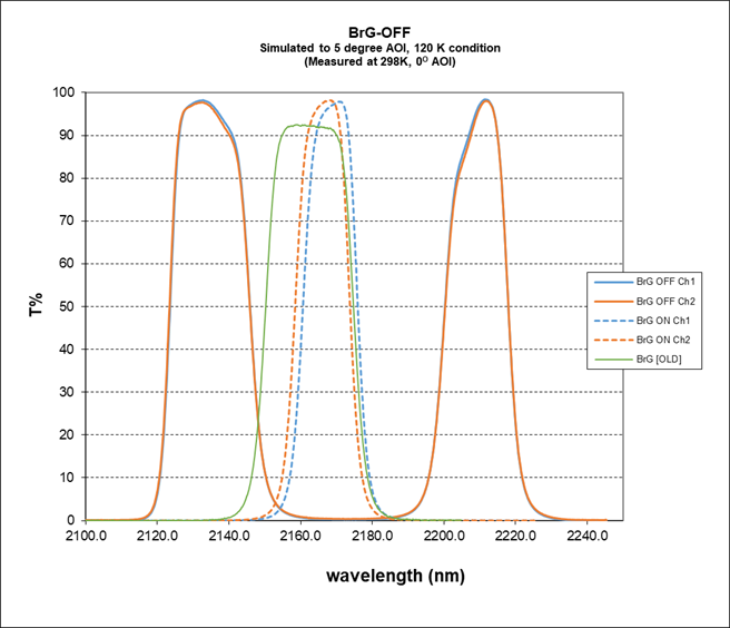 |
|
2.139 & 2.214 | 0.023 & 0.018 |
| NB2315(1) | 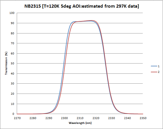 |
|
2.317 | 0.026 |
| (CO(1,7)) | 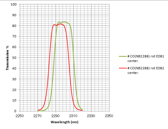 |
|
2.298 (ch1) 2.292 (ch2) | 0.023 |
Notes:
- They are originally the user (carry-in) filters. Please read the policy for use.
- The data are not from the direct measurement but from the datasheet by supplied companies.
- The transmission curve presented here is the data directly measured from the dome flat.
- The background level of NB119 filter is very dark. Minimum exposure of ~30 minutes is sometimes required to reach the background-noise-limited case. Sky subtraction is generally difficult due to the change of the background.
- The bandwidth of the new BrG_ON filter is narrower than the existing BrG filter. It is intended to be used in pairs with BrG_OFF; see the image of the BrG_OFF filter transmission curve for their relationship. Note that they are newly introduced in May 2025 as carry-in filters by the team led by Dr. Kumiko Morihana (morihana(at)naoj.org: change (at) to @). Those who wants to use the filter should give acknowledgement to Dr. Morihana when published.
- The filter is prepared by the team led by Dr. Yumiko Oasa (Saitama Univ) and is available to users from S27A with a permission of the team. Those who want to use the filter should contact her (email to yumiko.oasa(at)mail.saitama-u.ac.jp: change (at) to @). As of writing this, the filter is not installed yet, and so performanfce evaluation is not done. Thus, the use of the filter is under the shared-risk policy.
- Temporarily removed. If you need to use the filter, contact the primary SA at least 1 year before the actual use.
Sky Counts by Each NB Filter
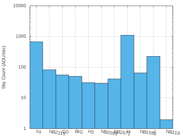
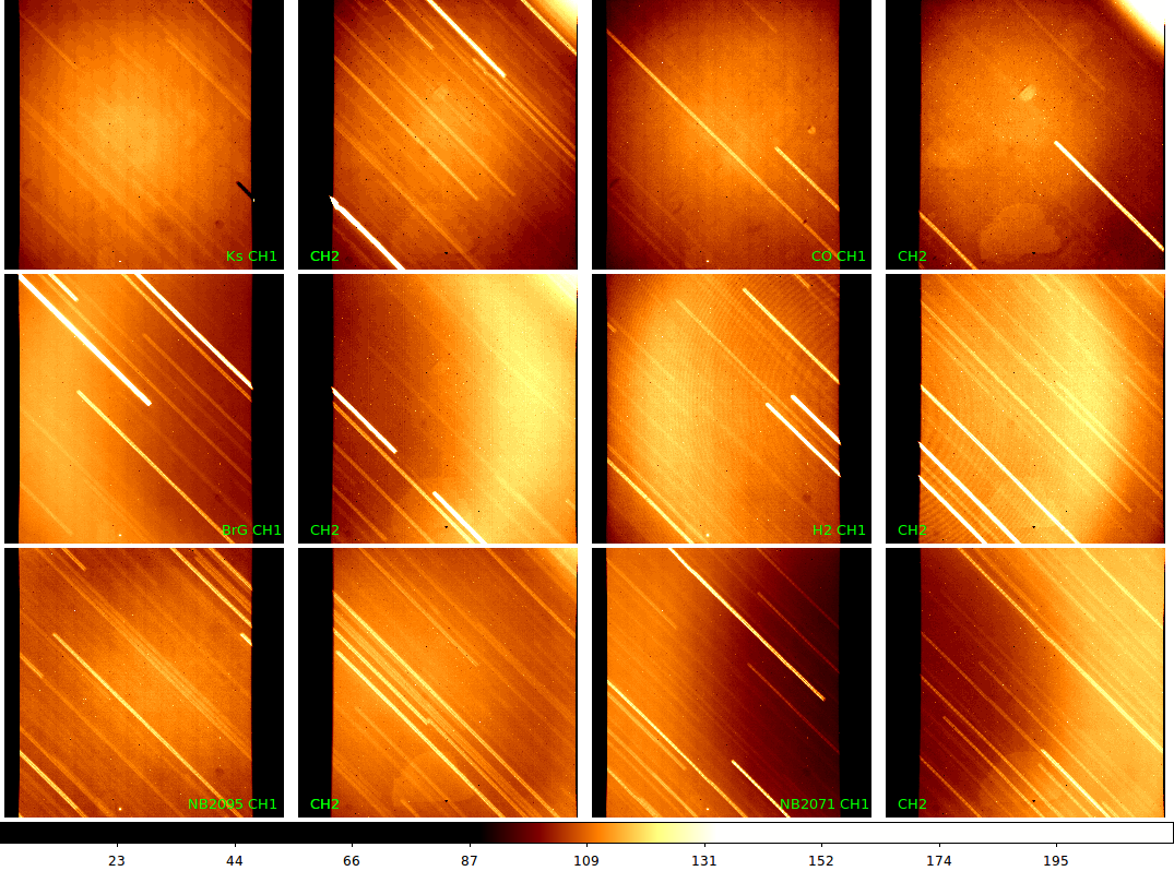
The measured sky counts and pattern for (some of) the NB filters can be found here and here.
The Shift of Transmission Curve within the FOV
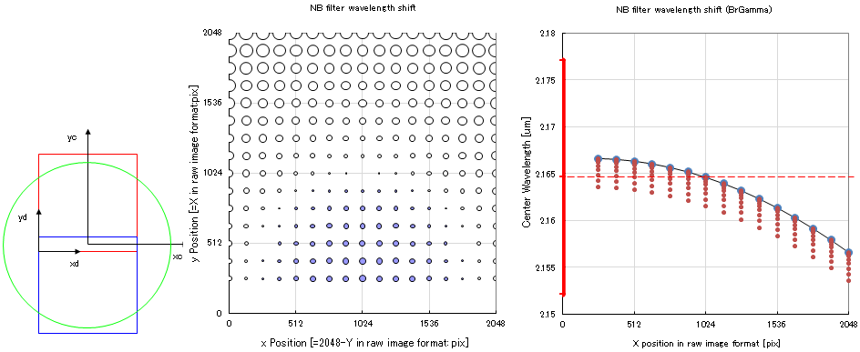
The actual CWs for these filters will change as a function of the angle of incidence (AOI) to the filter. This means that the filter transmission will have significant dependence with the position on the image. As the filters are put on the collimated beam, the AOI will change from 0 (pointing center) to 11 deg (farthest edge), causing the maximum shift of ~200 Å for H2 filter case. Below is the example of the calculated shift for BrG filter.
- The result of the actual measurement for central wavelength and band width by dome flat lamp (executed in Oct 2012, Nov 2013) is available here.
- The Microsoft Excel worksheets for wavelength shift calculation (summary as well as each filter) are also available. If you need more information, please contact the Support Astronomer.
K-Continuum and ND Filters
The K-Continuum filter and the ND filters were decommissioned in 2022. As for Kcont filter, we instead introduced the K3 medium-band filter (MBK3). Please use the filter instead.
The ND filter (OD~0.7) was also decommissioned. If you have a request to use the ND filter, contact the primary SA well before (~1 year) the actual use.
User Filters
We welcome the user filters. The detail and the user filter policy can be found in the User Filter Policy page. Please first contact the primary SA if you are planning to make a carry-in filters, because the vacant slots are quite limited now.
The Old MOIRCS Filter Page
The old "MOIRCS Filter" page (for old detectors till May 2015) can be found here.
Please note that all data on these pages are subject to change as the evaluation of the performance of MOIRCS progresses.