Instrument
Overview

The PFS instrument consists of several components. See also here.
Wide Field Corrector (WFC)
The WFC is an optical system consisting of 7 lenses designed to correct imaging aberrations for Hyper Suprime-Cam (HSC) and PFS. The largest lens has an effective area of 820 mm (32 inch) in diameter and the total lens system is 1845 mm (73 inch) long.
Prime Focus Instrument (PFI)
Together with the WFC, the Prime Focus Instrument (PFI) is installed on the prime focus of the Subaru telescope.
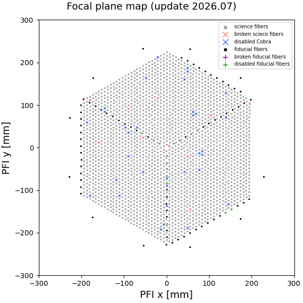
At the focal plane, ~2400 fibers are paved across the ∼1.25 deg2, hexagonal-shaped field of view. There are two types of fibers, 2394 science fibers and 96 fiducial fibers. Each science fiber is attached to a small actuator, the fiber positioner (see below), and moved to the location of the targets on the focal plane. The fiducial fibers are fixed in their position and used as position reference when the science fibers are moved. The fibers are equipped with a microlens on their surface to make the F-ratio slower (F/2.8) and reduce degradation of image quality after passing through the long fiber cable.
A ∼54mm-thick glass plate, the so-called field element, is installed in front of the fibers to achieve the same image quality as HSC. The field element has opaque dots to hide the fibers behind them and prevent light from coming to the fibers. By doing so, more sparse spectra can be taken by the spectrograph, which enables better understanding of the spectra on the detectors.
Surrounding the hexagonal shaped field of view, six imaging cameras are accommodated for sky-field acquisition and auto guiding. Six calibrations lamps (one quartz lamp for continuum and five arc lamps, Kr, Ar, Ne, Xe, and HgCd) are installed on the top of PFI to uniformly illuminate the screen on the dome ceiling.
Fiber Positioner ("Cobra")
Each science fiber tip is controllable in-plane by the fiber positioner, nicknamed "Cobra", which is a piezo actuator with two rotational axes. The fibers are arranged in a hexagonal pattern with 8mm separation, with each fiber being able to cover a region of 9.5mm in diameter. The overlap between adjacent regions enables 100% sky coverage within the hexagonal field.
Focal plane map
Below is a figure showing the fiber distribution on the PFI focal plane highlighting the broken/disabled fibers. See the legend for details.
Limitation of Rotator driving range and dead zone
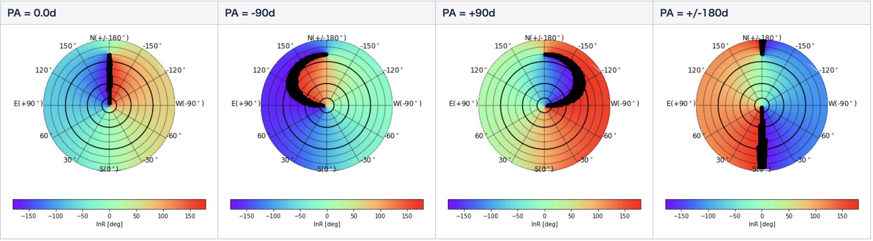
PFS has a constraint in the range of the rotator angle, InsRot < -174.0 deg, and > 174.0 deg, that is, +/-6 deg from 180 deg. We call it the dead zone. The dead zone causes blind regions on the sky, which varies depending on POpt2's position angle.
The figures show the blind zone with black shadow on sky with Position Angle (PA) = 0.0, -90, +90, and 180 degrees.
Spectrograph System (SpS)
The four identical spectrograph modules provide the simultaneous measurement of ∼2400 spectra. Each spectrograph module has three independent channels (blue, red, and near-infrared) separated by two dichroic mirrors so that the whole system can cover a wide wavelength range from 0.38μm to 1.26μm in one exposure. Resolution is low (∼2300-4300) using a Volume Phase Holographic (VPH) grating. By switching the VPH grating, the red channel can operate in medium resolution mode (∼5000).
The Spectrograph modules also have a system to back-illuminate all ~2400 science fibers to position the fibers on the Subaru prime focal plane. The Spectrograph modules are accommodated in a dedicated clean room on the forth floor of the Subaru dome building. In the clean room, the temperature is controlled at 4±1 °C to minimize the thermal effect on optics and mechanics.
Constraints on exposure time
The maximum exposure time for a single exposure is 900 seconds for both Classical and ToO mode observations. Even if a single fiber design is to be observed for a long duration, the fibers must be re-positioned approximately every 30 minutes. Therefore, integrations for a single fiber design should be carried out as follows:
- For T_total <= 1800 seconds: two exposures of T_total/2 each
- For 1800 seconds < T_total ≤ 3600 seconds: two sets of exposures, each with two exposures of T_total/4 (with fiber repositioning between the two sets)
- For T_total > 3600 seconds: repeat exposures of 2 × 900 seconds, with repositioning between each set
Ensure this is considered when preparing the target list and estimating the expected SNR using the ETC.
Fiber System
The fiber system consists of ∼2400 optical fibers which relay light collected at the focal plane to the four spectrographs located in the clean room. A fiber cable consists of three parts, to develop and operate the instrument easily. The first part is accommodated within PFI as fiber modules with their "Cobra" positioners, the second part is integrated to SpS as fiber slit assembly, and the third part is developed as long fiber cable routed on the telescope and in the dome building. The total length of each fiber is 65 meters, assembled into four groups providing 600 inputs to each spectrograph. In addition to the ∼2400 science fibers, the monitoring fibers are accommodated to check connection at installation.
Metrology Camera System (MCS)
The MCS is attached to the Cassegrain Focus of Subaru telescope and measures the positions of the fibers on the prime focus. MCS can take an image of all ∼2400 fibers in a single exposure using a large format (8960 pixels x 5778 pixels) CMOS camera. The primary mirror of MCS is 380mm in diameter to average out the local surface error of WFC.