The Subaru PIAA lab prototype

The Subaru PIAA lab prototype |
|
Home |
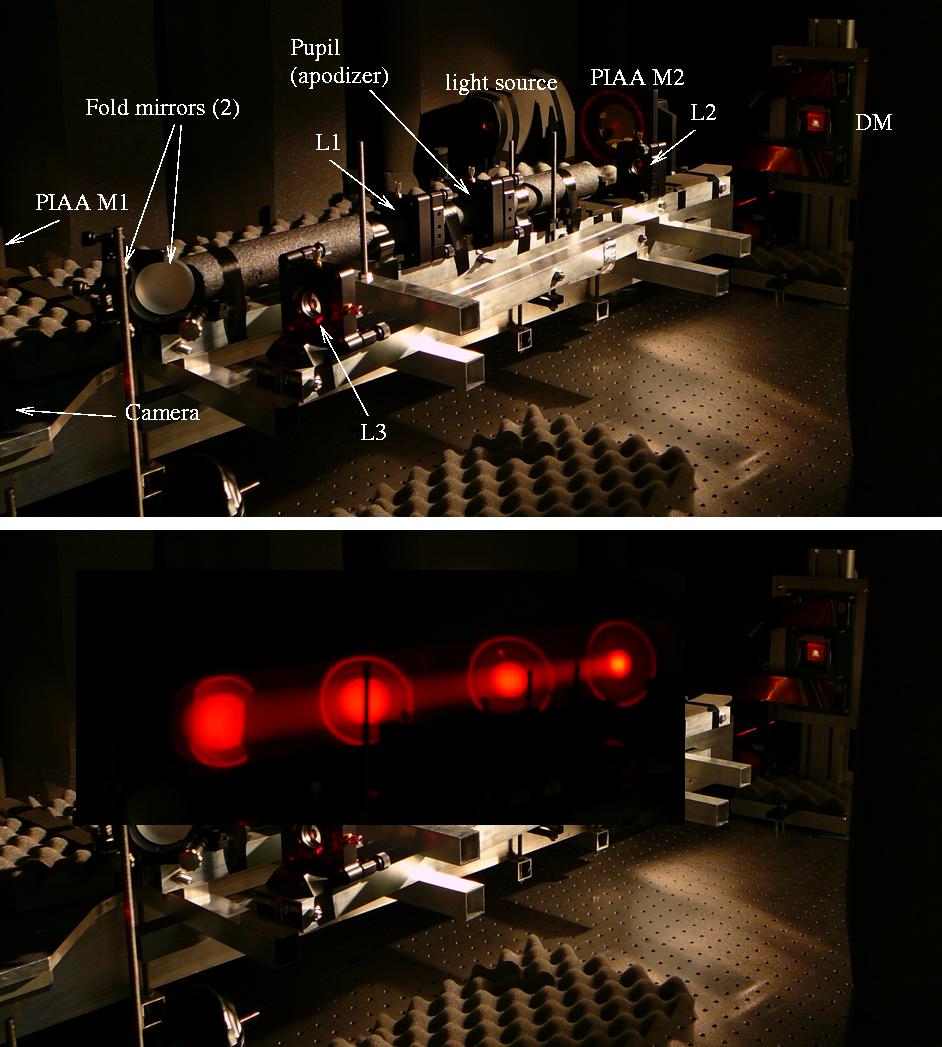
Show content only (no menu, header) This page describes the PIAA system prototype at Subaru Telescope. This lab was de-activated in Feb 2009, as its primary goal (demonstrate PIAA coronagraphy to 1e-6 contrast) was completed. PIAA-related activities at Subaru Telescope are now focused on the development of the Subaru Coronagraphic Extreme-AO (SCExAO) system. Laboratory demonstration of PIAA for ultra-high contrast for imaging of exoplanets from space is now mainly done at NASA Ames and NASA JPL. The Subaru prototype was a precursor to the systems at NASA Ames and NASA JPL, and I work closely with these two groups to advance PIAA technology for space. Overview
More detail can be found in the following pages: Lessons learned / surprisesTemperature control: worked very well, but ...The temperature control system worked extremely well: we were eventually able to maintain temperature stable to mK level for long periods of time.Details of the system hardware can be found here (note: this page describes the early results, and temperature stability was even better in later runs). ... be extra careful with leaksOur design was supposed to be leak-proof. The optical bench was higher than the water tank, and the pumps are pulling water instead of pushing it, so if there is a leak on the bench, air gets in the line instead of water getting out. What we didn't plan was that a small leak appeared in one of the connectors near the tank, just in the wrong place, where the pipe is lower than the water level on the tank. Since the pumps were off at the time, the water pressure was slightly positive in that part of the pipe, so water slowly leaked and the tank emptied.The lowest piece of electronics was the UPS, which was directly on the ground. A 3 to 5mm thick pool of water formed below the UPS, just high enough to touch the main electronic board of the UPS. A wet UPS does not die quietly - it fights until death and tries hard to keep devices powered. This blew a few fuses in electronics downstream, and cost us about 3 weeks of downtime. ... moving bubbles and pump vibration can shake thingsDue to a small leak somewhere in the line we had small bubbles circulate through the pipes. The leak was very small, and the bubbles were both small and infrequent. As the bubble moved through the pipes and took turns, it was however moving things around. We also had serious problems early on with a large pump which was pulling the water in a non-smooth way, creating vibrations on the bench. We built an attenuator to mitigate the problem (a long vertical sealed pipe, with air at the top - the water goes in and out from the bottom, and air at the top dampens vibrations): this helped a lot but did not solve the problem entirely. Later, we used smaller pumps which have a higher vibration frequency: this worked very well, and a few meters of soft plastic tubing efficiently dampened the residual high frequency vibrations/pressure changes.Helium : not as simple as we thoughtWe hoped to make our experiment very stable by filling the chamber with Helium. The goal was to minimize turbulence. Helium is thermally very conductive, so it tend to conduct heat directly instead of forming turbulence. Helium's refraction index is aslo much closer to 1.0 than air.Our attempts at making things better failed. First, Helium wants to leak out, and we never managed to keep it in for long periods of time. If we had planned this from the beginning, this would have worked (maybe, maybe not - see below), as we would have built a very tight tank. But we simply put plastic bags on top of our chamber. Because of the leaks, we had to continuously refill, and the Helium coming out of the Helium tank was colder due to the pressure change, so it was not very stable. Other problem: unless you can be sure that you have nearly 100% Helium, a mixture of mostly Helium and a little bit of air is much worse than air . The vastly different index of refraction between air and Helium means means that even a little bit of air will make things really bad. As we were filling up the cavity with Helium, the first thing we noticed was that the beam went off our field of view. This was due to the vertical gradient in the index of refraction: air concentration decreases with z. We kept filling up the cavity, and eventually, the beam came back to the camera. But it was not stable. We think that because we have foam inside of the cavity, a small quantity of air trapped in the foam was slowly raining down on the beam, creating a lot of turbulence. Another thing to be careful about: in Helium, the electrical breakdown voltage is about 1/3 of what it is in air, so arcing is 3x easier. Since our experiment includes a DM powered by high voltage (150V), we had to be very careful and limit our max voltage to 100V. Moon and Sun: tides can move things around !This was the biggest surprise: after making sure the bench was very immune to environmental disturbances, we found out that our beam was still moving. The residual motion showed a ~12 hr period, but was not entirely periodic. We eventually matched this to the change in the vertical component of the gravity vector due to the combined action of the Moon and Sun. A fairly large piece of insulation foam was pushing on a corner of the DM tip-tilt mount, causing the problem. We changed modified the foam support and the problem was solved.The figure below shows the PSF center motion as a function of time (x-axis, unit = day), compared to the vertical component of the gravity. Y-axis units are arbitrary. The PV gravity modulation is about 1e-7 (relative). 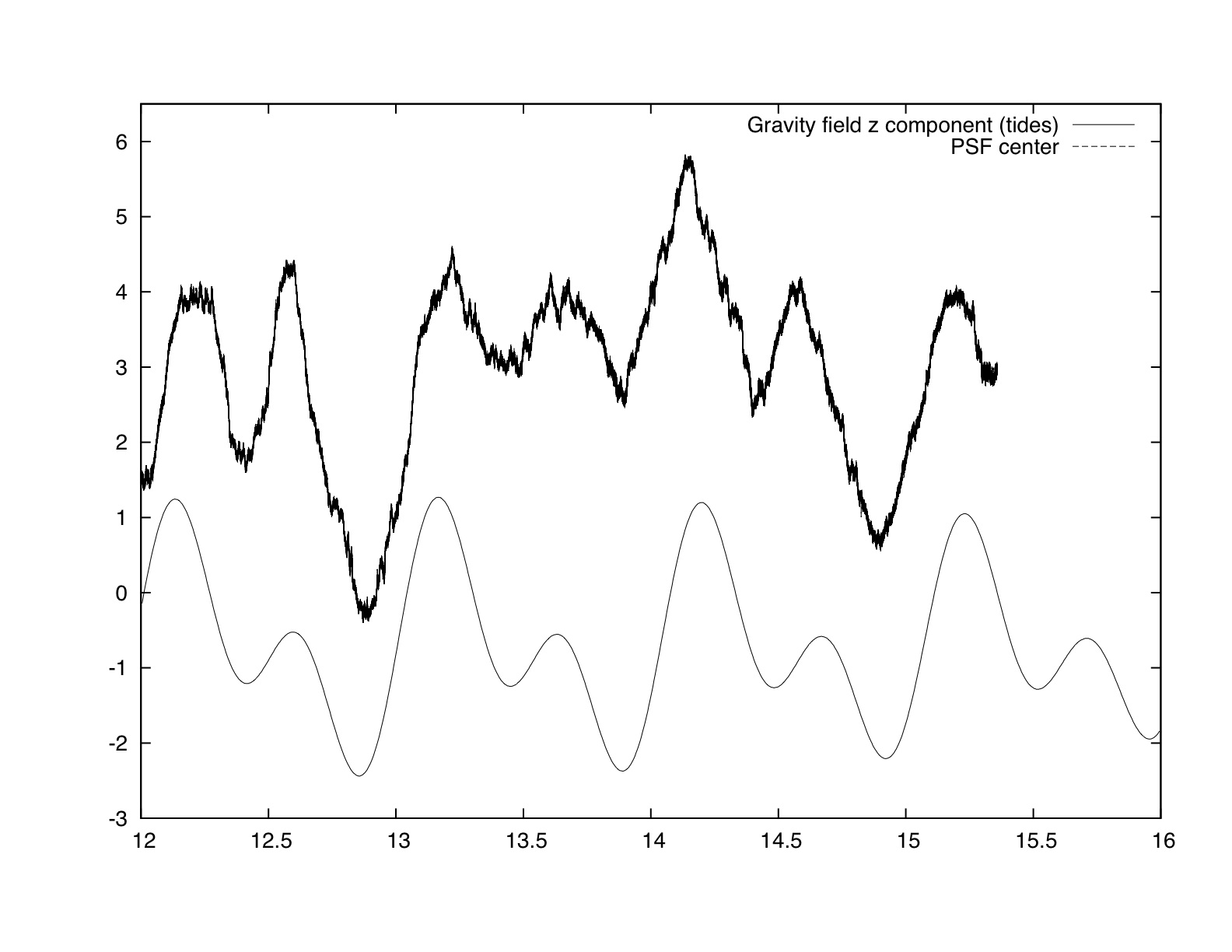
Page content last updated: 27/06/2023 06:35:52 HST html file generated 27/06/2023 06:34:37 HST |