|
Show content only (no menu, header)
PIAA coronagraph architecture
There are several possible coronagraph architectures using PIAA optics. Figure 1 shows both the minimum PIAA coronagraph conceptual architecture, and a full architecture. The minimum architecture simply produces an image after the PIAA optics. The central source's light is highly concentrated in a single narrow diffraction spot, allowing much fainter off-axis sources to be imaged. This simple architecture, which is described in Guyon 2003, is however limited in both performance and manufacturability :
- The PIAA optics are very difficult to manufacture when designed for high contrast. In this PIAA design, the outer edge of the first PIAA mirror is highly curved. This feature, which is essential for obtaining the desired apodization, is extremely difficult to polish.
- Chromatic diffractive propagation of the wavefront at the edge of the beam prevents high contrast in broadband light. This effect was first identified in Vanderbei 2005
- The off-axis image quality is poor, as first shown in Guyon 2003
- This configuration, as shown in Figure 1, does not have a focal plane mask and requires the camera detector to record a high contrast image.
 |
Figure 1: Two example of PIAA coronagraph system architectures. Both architectures use a set of aspheric optics (top left) to perform lossless apodization of the telescope beam. The minimum PIAA coronagraph system (top right) consists of a PIAA apodization unit introduced before the instrument's focal plane detector array. A full PIAA coronagraph system (bottom) can also include an apodizer, a focal plane mask, a pupil stop and an inverse PIAA optics unit.
|
These issues can be solved or mitigated with a more complete PIAA system design, as shown in the bottom of Figure 1. A complete PIAA system includes the following components in addition to the PIAA aspheric optics:
- A focal plane mask followed by optics to re-image the focal plane on the science detector. The focal plane mask removes the light from the central star and does not require any optical component or detector located downstream of the mask to support high contrast imaging
- An apodizer located after the PIAA optics, but before the focal plane mask. The role of the apodizer is to share the apodization with the PIAA optics. This allows re-design of the PIAA optics to greatly improve manufacturability and reduce the chromatic propagation effects at the edge of the beam. These gains are documented in Pluzhnik et al. 2006
- A pupil mask (Lyot mask) located after the focal plane mask. This pupil mask allows the PIAA coronagraph to be designed as an Apodized Pupil Lyot Coronagraph which achieves starlight suppression with both the focal plane mask and the Lyot mask, and offers superior performance
- A set of inverse PIAA optics to recover a diffraction limited PSF over a wide field of view. This set of optics, first suggested in Guyon 2003, was demonstrated in the laboratory by Lozi et al. 2009
- A complex amplitude focal plane mask to compensate for the chromatic change in PSF size at the focal plane.
 |
Figure 2: Five possible PIAA coronagraph architectures, approximately ordered from top to bottom in increasing performance and manufacturing ease.
|
Figure 2 shows five possible PIAA system configuration implementing none (a), a subset (b-d) or all (e) of the components listed above. Figure 3 shows how these architectures compare in both performance and technical difficulty (mostly manufacturing). The manufacturing challenges associated with each of the five architectures are listed in the table shown on Figure 4.
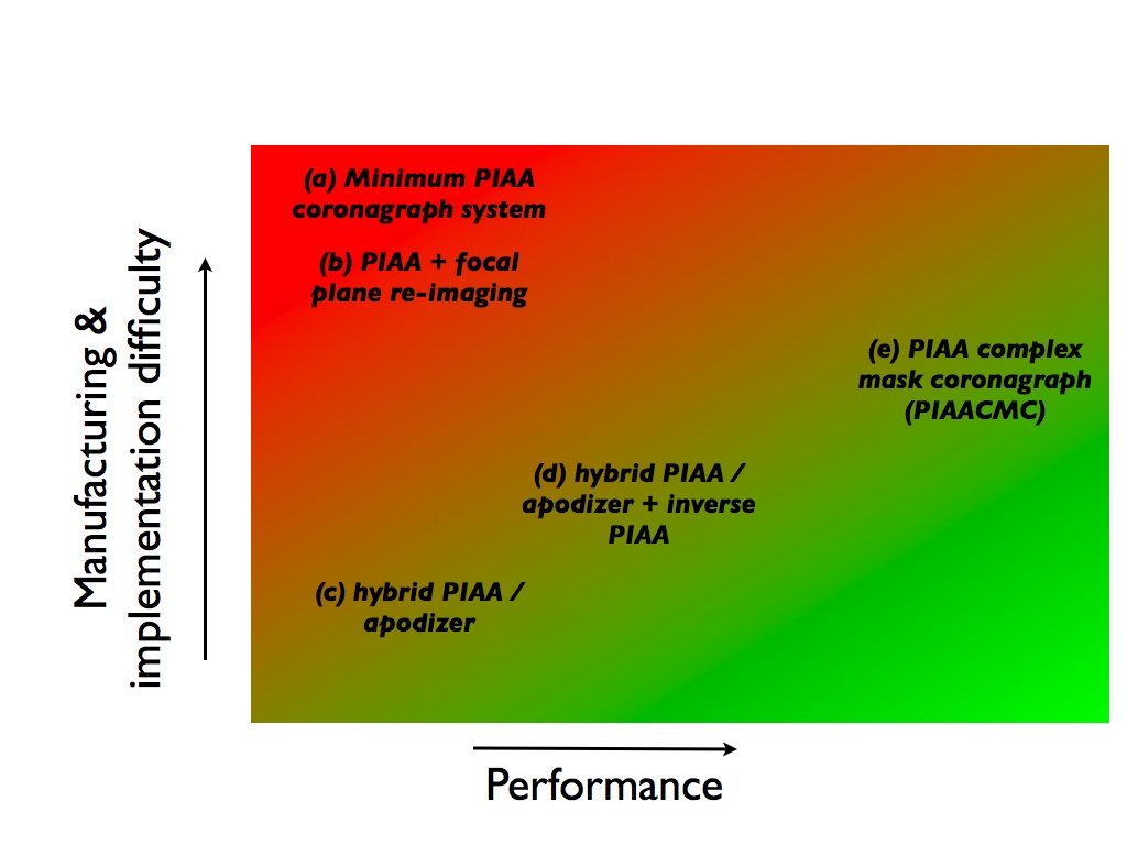 |
Figure 3: Approximate location of the five architectures shown in Figure 2 on a 2-D plane with performance (x axis) and degree of technical difficulty (y axis) coordinates.
|
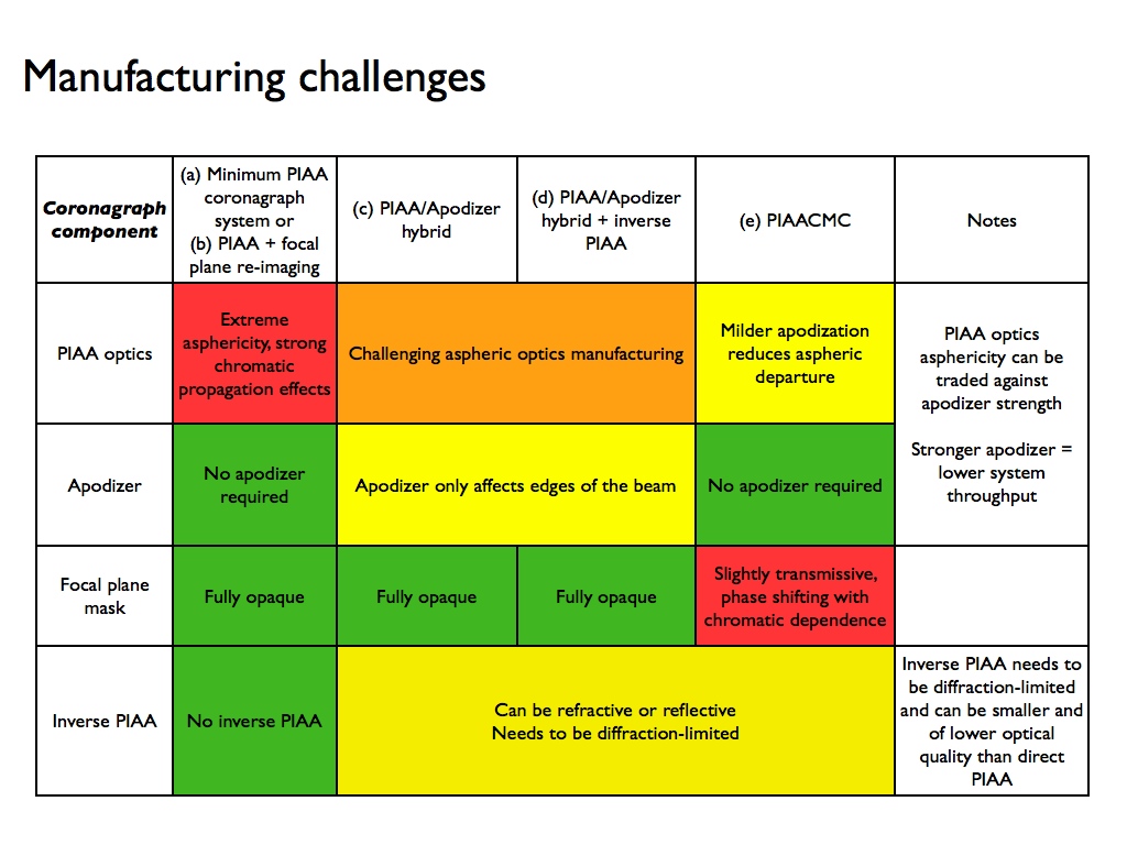 |
Figure 4: For each of the four architectures, manufacturing challenges are different, as shown in this table.
|
Wavefront control in a PIAA system: importance of deformable mirror location
The outer working angle (OWA) is defined by the furthest (from the optical axis) speckles that the DM(s) can cancel in the science focal plane. In non-PIAA coronagraph and with actuators organized on a regular square grid, the OWA is therefore (N/2)x(λ/D), where N is the number of actuators along the diameter of the pupil. The OWA then appears in high contrast adaptive optics (AO) systems as the size of the "high contrast" box in the focal plane.
In a PIAA system this straightforward relationship becomes more complicated, due to the pupil remapping. The location of the deformable mirror in a PIAA system can therefore have a large impact on the outer working angle (OWA) of the system. Because of the remapping, the local radial slope of the wavefront finds itself magnified by the local value of the apodization function (Martinache et al. 2006). If one notes A(r) the radial apodization profile after PIAA remapping (in square root of the intensity), the post-PIAA wavefront radial slope of an off-axis source (angular separation α, azimuth θ0) therefore writes as:
|
δφ(r,θ)/δr = α A(r) cos(θ-θ0).
|
(equ 1)
|
|---|
Figure 5 illustrates the impact of the remapping on the wavefront slope: in the inner part of the beam, where A(r) is maximum, the slope is amplified by a factor βa > 1, while near the outer edge of the beam, it is reduced by a factor βr < 1. Typical values for these factors are βa = 3 and βr = 0.3. Because in the post-PIAA beam, most of the light is concentrated toward the center of the beam. It is therefore this part of the wavefront, and the factor βa that will define the location of the off-axis image pseudo-core.
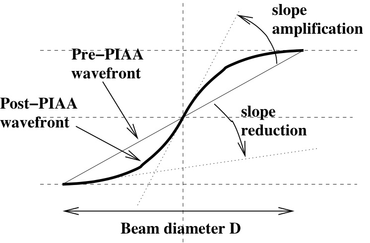 |
Figure 5: Slope amplification and reduction factors in a PIAA system. The remapping introduced by a PIAA system amplifies the wavefront slope at the center of the apodized beam (where most of the light is located) and reduces the wavefront slope at the edges of the beam.
|
These factors can quantitavely be used to estimate the OWA for several PIAA+DM system configurations (Figure 6), in which the DM(s) must correct for wavefront errors both before and after the remapping :
- Configuration 1 (DM located after the PIAA optics, no inverse PIAA). The angular distance α of each off-axis source perceived by the deformable mirror is amplified by βa. The OWA of this configuration is therefore reduced by the same amount, that is (N/2)/βa elements of resolution. Beyond this separation, the DM does not have sufficient actuator density at the center of the pupil: if the actuators were mapped to the entrance of the PIAA, they would be too large at the center of the beam.
- Configuration 2 (DM located before the PIAA optics, no inverse PIAA). If the actuators were mapped to the output of the PIAA, we find that the actuator size at the edge of the apodized beam is divided by βr < 1 (the actuators are bigger), while they are considerably smaller in the center of the apodized beam. In the outer part of the beam, the DM sampling can only allow full control of speckles to radius r = βr x (N/2) x (λ/D), corresponding to OWA = (βr / βa) x (N/2) x (λ/D) on the sky. We note that a larger OWA can be reached if speckles are only corrected over a fraction of the field, and the the OWA limits given in this section only apply to a half field dark zone for a single DM correction or a full field dark zone for a dual DM correction.
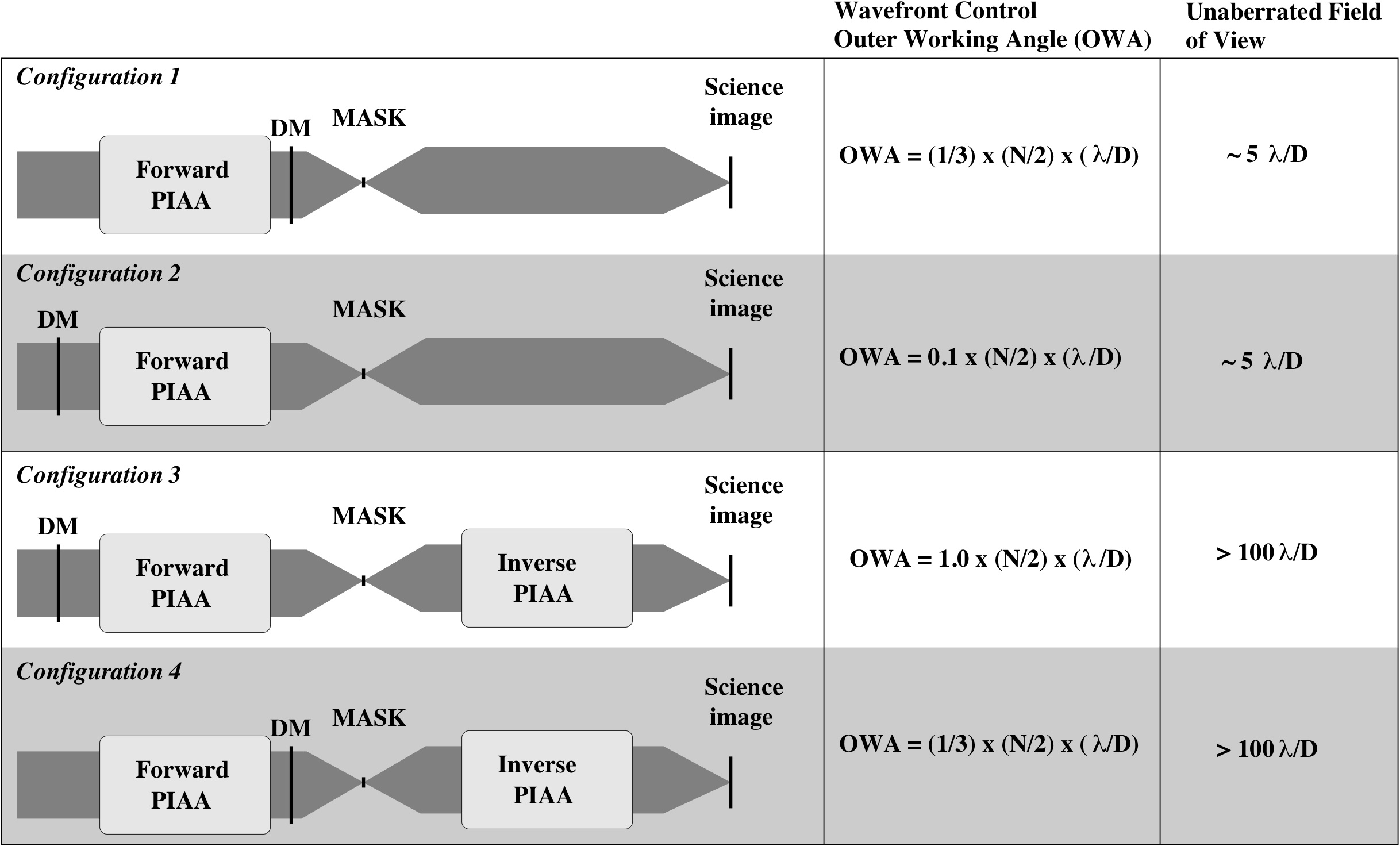 |
| Figure 6: Four possible architectures for a PIAA coronagraph with wavefront control. For each configuration, the outer working angle of the wavefront control system and the field of view imposed by remapping are given. The PIAA slope amplification factor βa = 3 and slope reduction factor βr = 0.3 are considered here. Configurations shown in gray (configurations 2 and 4) should be avoided (see text for details). The unaberrated FOV values are given assuming N=32 actuators across the pupil diameter.
|
In both configurations 1 and 2, the unaberrated field of view is limited to r ~ 5 λ/D by the field aberrations introduced by the PIAA optics. This effect is described in Figures 4 to 7 in Guyon et al. 05. There is therefore little advantage to increasing the wavefront control OWA much beyond this radius, although it can be beneficial to do so in polychromatic light to avoid chromatic speckles within the OWA due to non-linear frequency folding of speckles just outside the OWA (Giveon 2005). We note that the OWA and the unaberrated field of view are equal for N ~ 30 and N ~ 100 in configurations 1 and 2 respectively.
We now explore configurations including inverse PIAA optics to provide a wide unaberrated field of view (> 100 λ/D in radius as shown in Guyon et al 2005, Figure 11). In these configurations, the field of view for high contrast observations is limited by the OWA of the wavefront control system.
- Configuration 3 (DM ahead of PIAA optics). In this configuration, the inverse PIAA cancels the effect of the forward PIAA, and the OWA is equal to what it would be in a non-remapped system: OWA = (N/2) x (λ/D). The only role of the remapping is to create an intermediate step where starlight is efficiently removed by the focal plane mask.
-
- Configuration 4 (DM after PIAA optics). The OWA can be found by remapping the DM geometry in the plane ahead of the forward PIAA, where its actuators will be magnified by βa at the center of the pupil. The OWA, defined by the largest actuator in this plane, is therefore OWA = (1/βa) x (N/2) x (λ/D).
In order to optimize the use of a given number of actuators, the DM(s) should therefore be placed after the PIAA optics in a PIAA system without inverse PIAA optics (configuration 1), or before the PIAA optics if inverse PIAA optics are included (configuration 3). The configuration adopted in our laboratory demonstration is configuration 1 (DM after PIAA optics, no inverse PIAA optics).
Page content last updated:
27/06/2023 06:35:52 HST
html file generated 27/06/2023 06:34:37 HST
|