IRCS Polarimetry
Linear polarimetry with IRCS and AO188 is available in two settings (near-infrared [NIR] 0.95−2.5μm and thermal-infrared [TIR] 1.92−4.80μm), which are offered on a shared-risk basis. Users who want to propose polarimetry observation MUST contact Dr. Tamura (motohide.tamura_at_abc-nins.jp the PI of the NsIR waveplate unit) and the support astronomer before proposal submission.
Basic Specification
| Setting |
NIR (0.95−2.5μm) |
TIR (1.92−4.80μm) |
||
| Mode |
Imaging Polarimetry | Spectropolarimetry | Imaging Polarimetry | Spectropolarimetry |
| Band |
Y, J, H, K, K' |
zJH (R~705λ w/0.10'' slit) HK (R~442λ w/0.10'' slit) |
K, K', L', M', H2 1-0 S(1), Br gamma, H2O Ice |
K (R~869λ w/0.10'' slit) L (R~331λ w/0.10'' slit) |
| Pixel Scale |
20 mas / 52 mas |
52 mas only |
20 mas only |
52 mas only |
| FoV of Mask/Slit |
20 mas: 2 Strips of 4.4'' (W) X 21'' (L) 52 mas: 4 Strips of 4.4'' (W) X 54'' (L) [Layout] |
0.60'' (W) X 4.4'' (L) 0.15'' (W) X 4.4'' (L) 0.10'' (W) X 4.4'' (L) 0.225'' (W) X 4.4'' (L) [Layout] |
K, K': 2 Strips of
4.4'' (W) X 21'' (L) L', M': 2 Strips of 4.0'' (W) X 21'' (L) [Layout] |
0.60'' (W) X 4.0'' (L) 0.15'' (W) X 4.0'' (L) 0.10'' (W) X 4.0'' (L) 0.225'' (W) X 4.0'' (L) [Layout] |
| Retarder |
Quartz + MgF2 half-wave plate |
LiNbO3 + MgF2 half-wave plate |
||
| Polarizer |
LiNbO3 Wollaston prism |
|||
Exposure Time Guide Line
The limiting magnitudes of polarimetry observations are generally 5-7 mag brighter than the corresponding non-polarimetry observation (i.e., normal spectroscopy or imaging). The signal-to-noise ratio (S/N) on the flux (not per waveplate position) required to obtain a polarization accuracy of dP is estimated by: S/N = sqrt(2)/(dP x Peff), where Peff is the polarization efficiency. For example, to obtain the polarization accuracy (dP) of 0.5 %, a S/N of about 283 in total is required when Peff ~ 1 (i.e. 100 %). In addition, for thermal infrared observation, the background noise is significantly increased due to the warm waveplate and the sensitivity will be degraded. For dP = 0.5 % with 1 hr exposure, the estimated sensitivities are Y~19.8 mag, J~20.7 mag, H~20.0 mag, K~19.5 mag, L'~14.5 mag, and M'~10.2 mag for imaging polarimetry and zJH~12.9 mag(J) | 12.0 mag(H), HK~12.1 mag(H) | 11.4 mag(K), K~10.9 mag, and L~6.1 mag for spectropolarimetry (per pixel) when Peff = 100 %. These values do not include the instrumental polarization uncertainty.
Polarization Efficiency and Instrumental Polarization
Polarization Efficiency
The polarization efficiency strongly depends on the AO188 image rotator angle and the wavelength as shown in the figure below. Both imaging and spectroscopy polarimetry modes should be operated around 0 degree or 90 degree of the image rotator. This restriction limits a range of the field position angle. Please note the strong dependency on the image rotator angle for J-band after the installation of NBS.
Imaging polarimetry mode
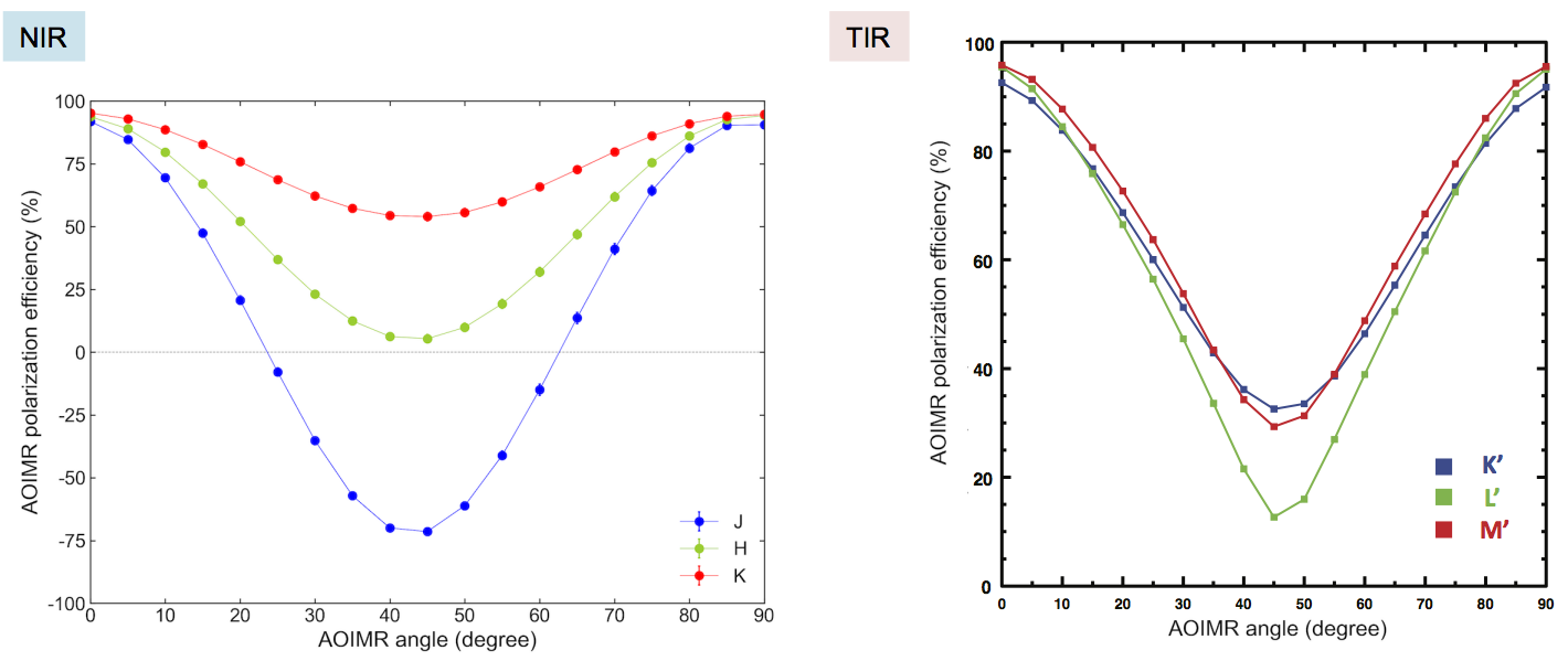
(Measurement: Telescope flat lamp + WPU Polarizer + each filter. No correction of degree of polarization of the polarizer. Note: TIR is before the installation of NBS.)
Spectropolarimetry mode
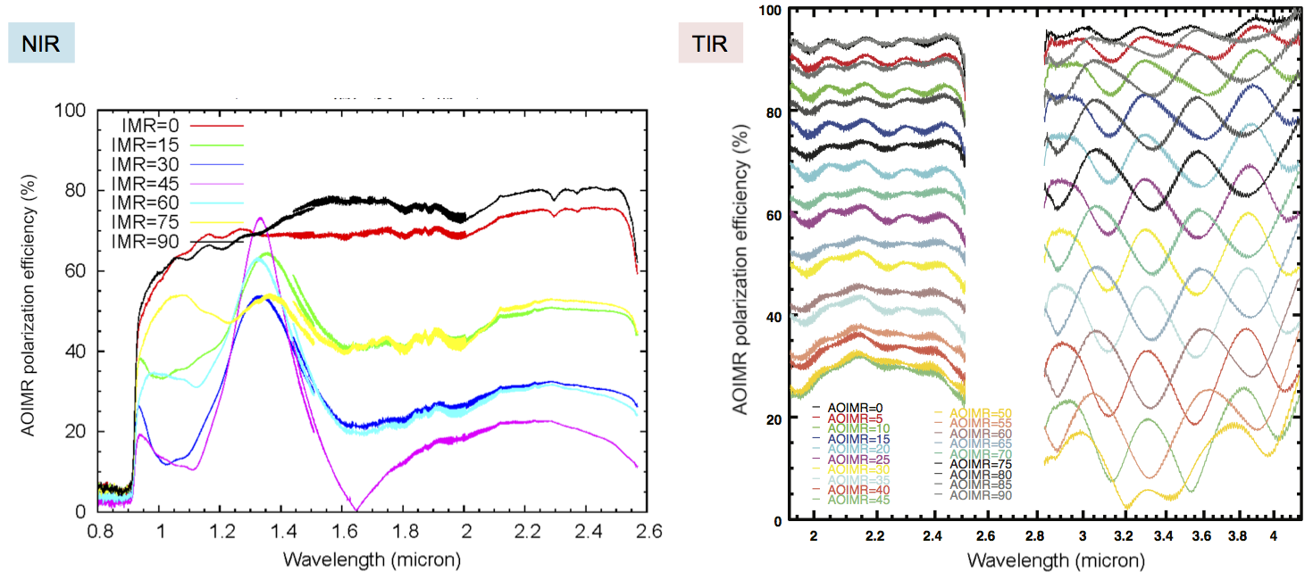
(Measurement: Telescope flat lamp + WPU Polarizer + each grism. No correction of degree of polarization of the polarizer. Note: Both plots are before the installation of NBS.)
Instrumental Polarization
From an unpolarized standard star measurement in NIR setting, most instrumental polarization is found to be due to the tertiary mirror.
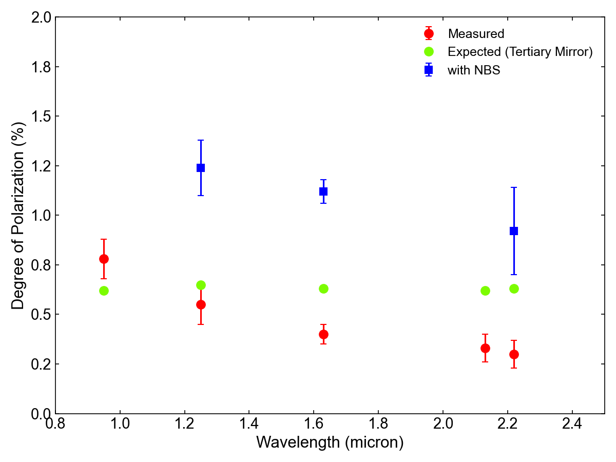
(Measurement with the unpolarized standard star WD0232+035 before installation of NBS, and HD30754 after installation. This is a preliminary result.)
(Position angle of instrumental polarization = the parallactic angle + 90 degrees)
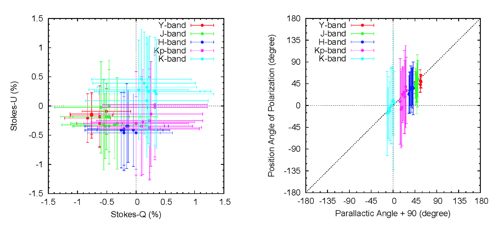
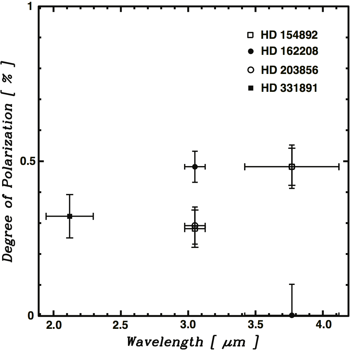
Also in TIR setting, the instrumental polarization is confirmed to be well below 1% with the following measurements with unpolarized standard stars (HD 154892, HD 162208, HD203856, and HD 331891).
Imaging Polarimetry
Y-, J-, H-, K-, and K'-band in NIR setting and K-, K'-, L'-, and M'-band in TIR setting are available for imaging polarimetry. PDI (Polarimetric Differential Imaging) function is not fully characterized and its performance has not been verified yet. Please note that the lateral chromatism of the Wollaston prism affects the PDI performance particularly at L'-band.
Layout of imaging polarimetry
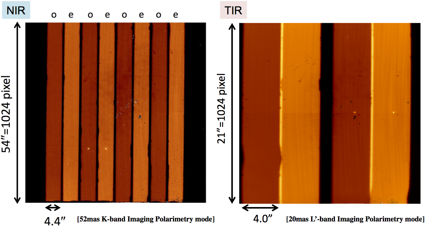
The FoV layout for imaging polarimetry is shown in the figure above. Please be advised that the FoV is overlapped at L'- and M'-band where the data is unusable.
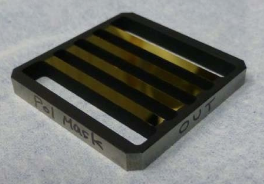 Polarimetry Mask (Tungsten carbide with gold coating)
Spectropolarimetry
zJH- and HK-Grism modes in NIR setting and K- and L-Grism modes in TIR setting are available for spectropolarimetry.
Layout of spectropolarimetry
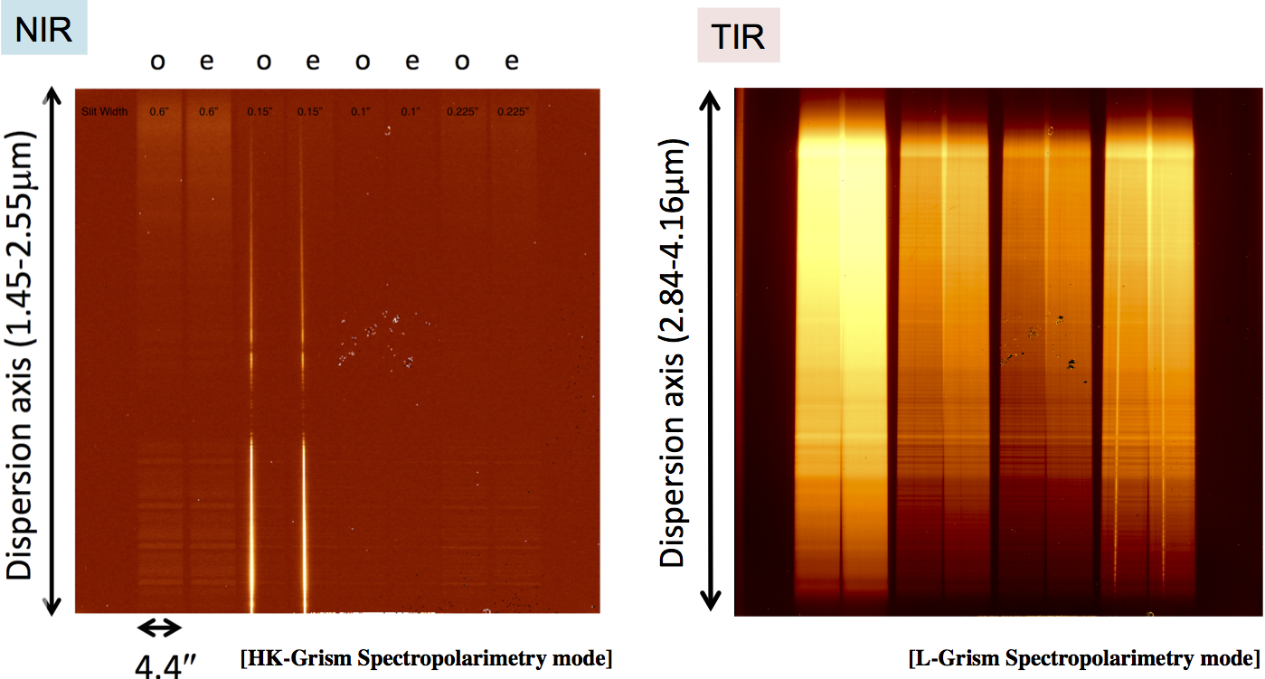
In L-Grism mode of TIR setting, the FoV is overlapped. The usable area is 4.0''.
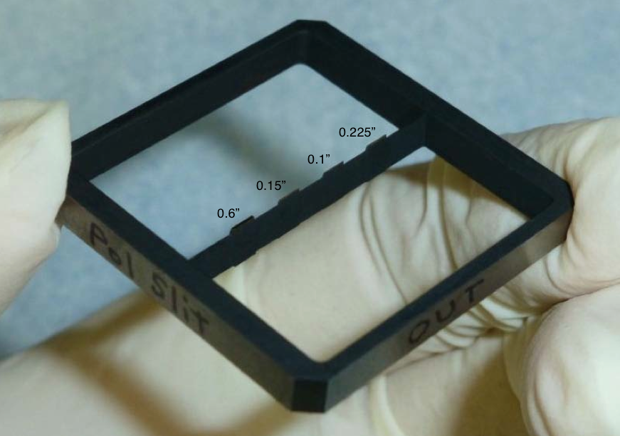 Polarimetry Slit (Tungsten carbide with gold coating)
Observation Procedures and Strategy
The following are the typical polarimetry observation procedures.
Standard procedure for linear imaging polarimetry
- Point the telescope to the target field.
- Take an image with K-band (or Kp-band) of target without Wollaston prism.
- Adjust the target position to the acquisition area on the polarimetry mask.
- Optimize the AO correction parameters.
- Do CheckField to change the optical elements (Filters/Wollaston prism) for observation and check the flux level with an exposure time.
- Do GetObject to take images with the following set of different angles of the half-wave plate (HWP) at each dithering point.
- 0.0 deg
- 45.0 deg
- 22.5 deg
- 67.5 deg
- Repeat GetObject to get enough S/N.
Standard procedure for linear spectropolarimetry
- Point the telescope to the target field.
- Take a K-band (or Kp-band) image of target without Wollaston prism.
- Optimize the AO correction parameters.
- Adjust the target position to the acquisition position on the polarimetry slit.
- Insert the polarimetry slit and do fine tuning of the target position on the slit.
- Do CheckField for the selected grism setting to check the flux level with an exposure time.
- Do GetObject to take the spectra with the following set of different angles of the half-wave plate (HWP) at each nodding point.
For the TIR mode, the additional 4 measurements of the waveplate angle are required to prevent from troublesome ripple features.
- NIR
- 0.0 deg
- 45.0 deg
- 22.5 deg
- 67.5 deg
- TIR
- 0.0 deg
- 45.0 deg
- 22.5 deg
- 67.5 deg
- 90.0 deg
- 135.0 deg
- 112.5 deg
- 157.5 deg
- NIR
- Repeat GetObject to get enough S/N.
The detection efficiency of polarization degree depends on the angle of the image rotator, so the polarimetry observation will be operated with keeping the image rotator angle around 0 degree or 90 degree.
References
- Watanabe, M. et al., "NIR AO Imaging- and Spectro-polarimetry with IRCS", Proc. SPIE 10702, 107023, 2018
- Terada, H. et al., "TIR AO Imaging- and Spectro-polarimetry with IRCS", Proc. SPIE 10702, 107022, 2018
The waveplate unit for retarders was originally prepared by the HiCIAO team and it is now commonly shared with IRCS and AO188. The IRCS polarimetry upgrade was proceeded in collaboration with Dr. Makoto Watanabe at Okayama University of Science and the retarder in TIR setting was provided by Dr. Mitsuhiko Honda at Okayama University of Science.
Please note that all numbers in this page are subject to change as the performance of this mode is better determined.