MOIRCS VPH Grism Information Page
Part of the page is for historical purpose. VPH-J, VPH-H grisms were replaced to LS_J & LS_H grisms in 2020.
VPH-K grism will be retired by the end of 2024 for VB_K grism.
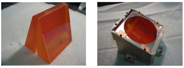
We have two high-resolution VPH grisms (VPH-Y & VPH-KNote) for the open-use observations (Note: VPH-J and VPH-H were retired in 2020 following the arrival of the better performance LightSmyth Grisms). The grisms were originally carry-in grisms, and the PI of each grism kindly donated them for open use. We thank Prof. Toru Yamada (VPH-K), and Dr. Kazuhiro Shimasaku (VPH-Y), as well as Dr. Noboru Ebizuka (manufacturing team leader) for their contribution to the community(note 1).
It is strongly recommended that the observer who used these grisms would give acknowledgement to providers on your papers when the data based on the grisms are to be published. And also, please refer the paper by Dr. Noboru Ebizuka below.
- "Cryogenic Volume-Phase Holographic Grisms for MOIRCS"
Ebizuka, N. et al. Publications of the Astronomical Society of Japan, 2011, Vol.63, SP2, pp.605--612.
We summarize the basic characteristics of these VPH grisms here. Users who would like to use the grisms should fully understand their basic characteristics. The use of these grisms is somewhat complicated: careless planning without understanding their characters may result in the failure of the observation.
The VPH grisms have three characteristics the users should be aware of: (1) a relatively peaky (narrow) transmission curve, (2) the strong dependence of the transmission peak wavelength with the position of the slit, (3) a large shift of the spectra to the spatial direction (in VPH-K). And also, the spectra by VPH grisms basically covers the entire span of the detector in the dispersion direction. Thus the starting and the ending wavelength of the spectra will change with slit to slit (by the slit position) for the MOS data. These characteristics make the mask design for objects that distribute across the MOIRCS FOV fairly complicated, so careful preparation and planning are required. See the "The Observation" part below for more.
Note (July 2024 update):
We successfully completed fabrication of the "VB-K Grism" under the support of the NAOJ Leadership Funding Program, and started to offer to the community from S24A. The new grism has similar spectral resolution but with high efficiency over much wider spectral coverage than the current VPH_K grism. Thus, we will retire the VPH-K grism by the end of 2024. The VPH-K users should consider using VB_K grism instead.
Specification
- The peak wavelength and throughput of the transmission curve will drastically change according to the slit position (see below).
- The shift of the spectra to the spatial direction is large for all grisms. The shift values (in pixels) are summarized in the table below. Note that the direction of the shift was changed in 2016 (due to the change of the installation direction that happened in late 2015).
- The order-sorting filter for VPH-Y is not necessary. For VPH-K we use the OC_HK or OC1.3 order-sorting filter. You can also use most of the imaging filter (NB and BB).
- The dispersion direction of the spectra on each detector has changed to be the same as that of the R500 and R1300 grisms in 2016; i.e., the decreasing [increasing] x-direction is the longer or redder wavelength for channel-1[2] raw image. Note that this was the opposite until 2015.
The table below describes the basic specification of grisms.
| VPH-Y | VPH-J [Retired] | VPH-H [Retired] | VPH-K [Retired] | |
|---|---|---|---|---|
| Resolution(1) | 3180 | 3020 | 2940 | 2680 |
| Straight-through Wavelength [um](2) | 1.017 | 1.235 (Channel 1) 1.236 (Channel 2) |
1.669 (Channel 1) 1.646 (Channel 2) |
2.178 (approx.) |
| Pixel Scale [A/pix] | 0.767 (Channel 1) 0.768 (Channel 2) |
0.955 (Channel 1) 0.958 (Channel 2) |
1.317 (Channel 1) 1.314 (Channel 2) |
1.94 |
| Shift of spectra in spatial direction [pix](3) | +24 (Channel 1) +72 (Channel 2) |
-36 (Channel 1) +53 (Channel 2) |
+137 (Channel 1) +77 (Channel 2) |
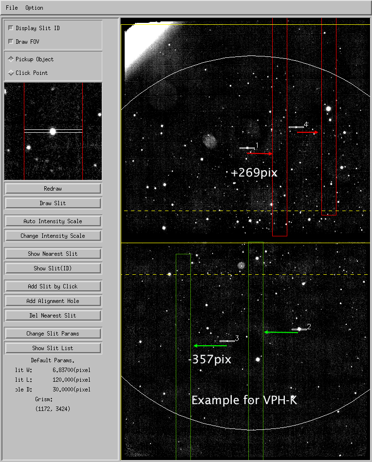
-357 (Channel 1) +269 (Channel 2) |
| Spectral Tilt (deg: CCW=+) | 0.3 (ch1) -0.5 (ch2) |
0.3 (ch1) -0.3 (ch2) |
1.1 (ch1) -0.5 (ch2) |
-1.5 (ch1) -1.5 (ch2) |
| Sensitivity(4) | 20.8 | 20.1 | 19.8 | 19.5 |
(1) From Ebizuka et al (2011) PASJ, S63, 605. These values are for 0.5"-width slit, and at the straight-through wavelength. Spectral resolution is roughly proportional with the slit width till 0.3" slit width (or less). If seeing is better than slit width, spectral resolution for object is basically determined by the object size in the slit.
(2) The value will shift slightly (30-50A level) with the slit position.
(3) In the preimage coordinate (=X_pre: the sign was changed on 9/30/2016). In the raw image coordinate, a positive shift in X_pre will be a negative shift in Y (raw). See the example for VPH-K case.
(4) Estimated sensitivities listed are for a 5 sigma detection per pixel (in 1-D spectra) in 1 hour of on-source background-limited spectroscopy (0.5" slit: mag/arcsec2 in vega mag). They are calculated using the measured MOIRCS efficiency and crude sky brightness between the OH night lines.
Grism Efficiency and its Characteristics
The figures below is an example of the efficiency curve for each grism (from Figure 9 of Ebizuka et al.). The system efficiency here includes all the loss by telescope and MOIRCS.
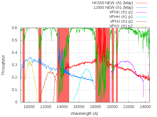
Figure 1: The system efficiency curves for VPH grisms. The same curves for R500 grisms are also shown for comparison. The sharp cut of the transmission curves for VPH is due to the detector edge. Note that the measurement of the VPH grisms is done for the slit near the center of the channel-1 detector. As is described below, the transmission curves for VPH grisms will change with the angle of incidence to the grism (= slit position). The data is based on the measurements in April and May 2016.
The important characteristic of these grisms is that the sensitivity curve will change with the X-position (in raw image coordinates) of the slit. The behavior for VPH-J, VPH-H and VPH-K is each shown in Figure 2. The peak efficiency value of the transmission curve is also known to change with X-position. The shift of the peak wavelength of the transmission curves is summarized in Figure 3.
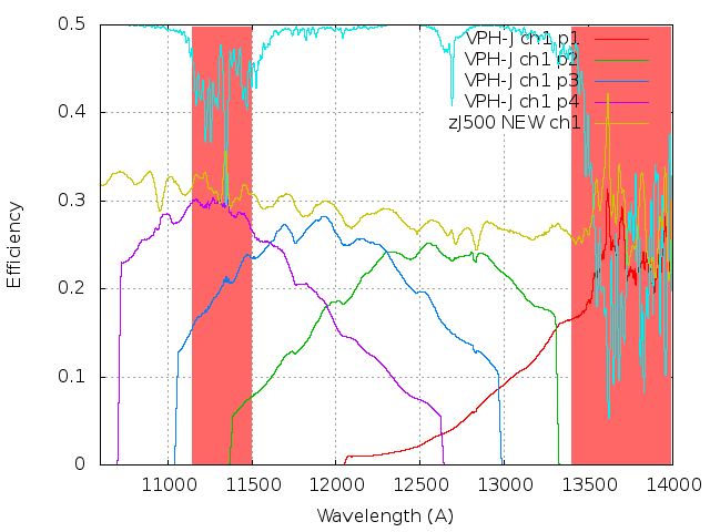
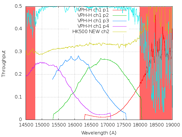
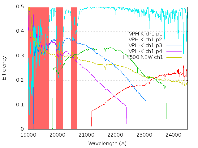
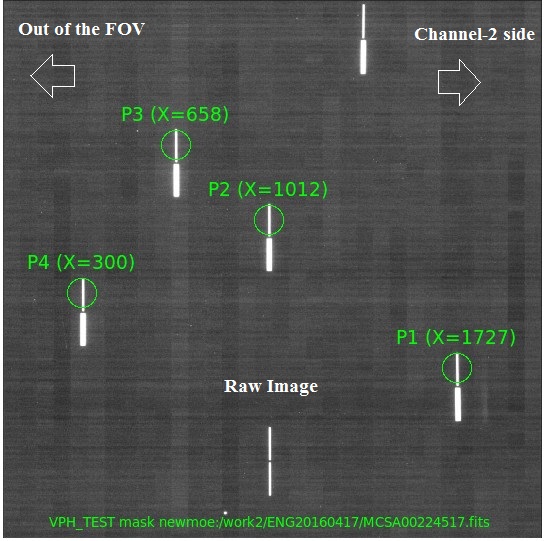
Figure 2: The shift of efficiency curve for VPH-J (left), VPH-H (center), and VPH-K (right) grisms with the X-coordinates of the slit (channel-1). Here the X coordinate of the slits (P1 to P4 in the figure) in raw image coordinate is X=1727 (P1: close to the mosaic boundary), X=1012 (P2: near center), X=658 (P3), X=300 (P4: outermost), respectively (also see here for the mask image). The wobbling pattern seen in VPH-J is from the ripple pattern of the OC-ZJ order-sorting filter. A sudden cut-off of each efficiency curve is due to the detector edge.
 |
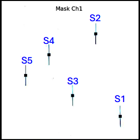 |
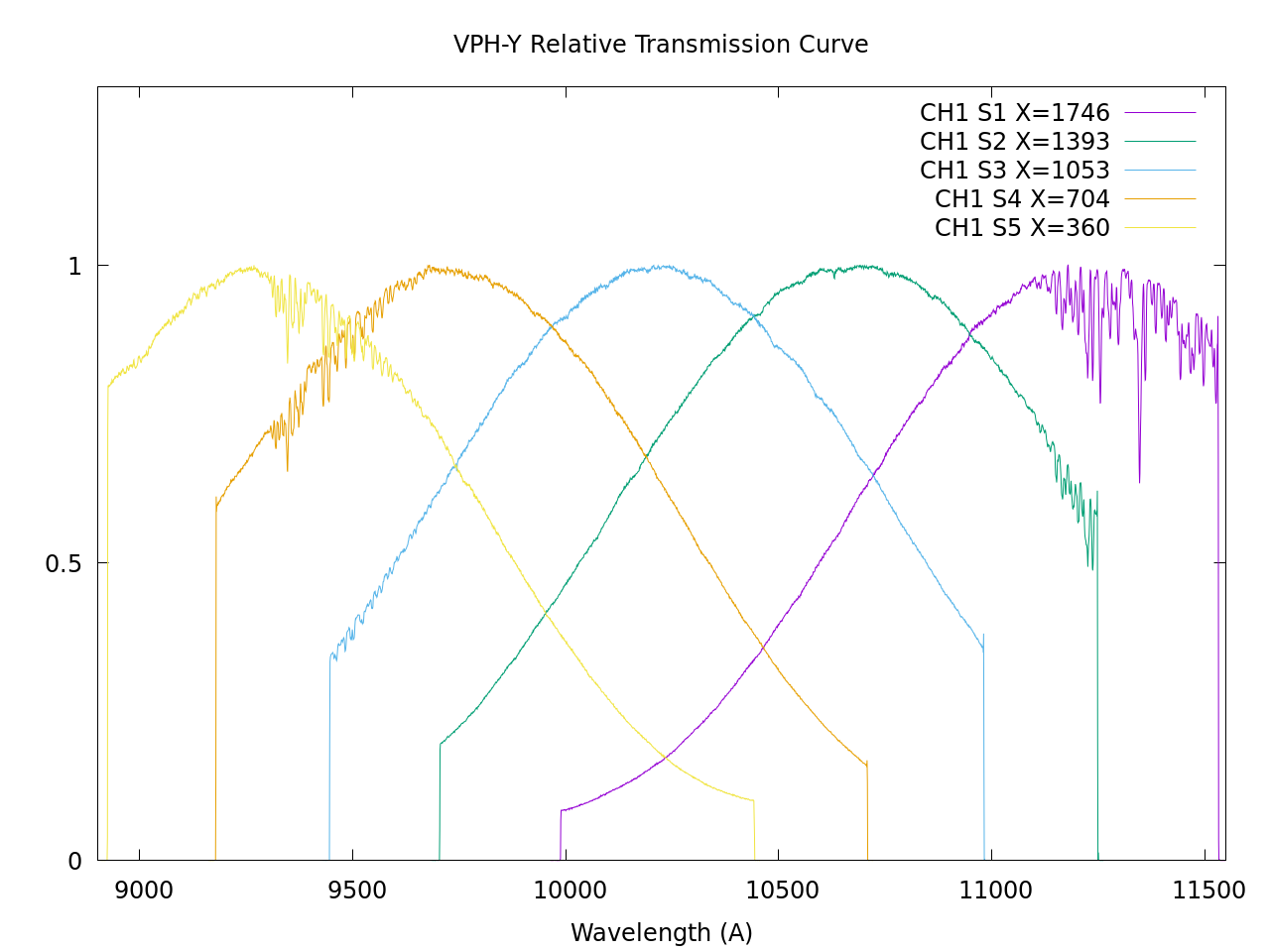
Figure 3: The figure shows the shift of the normalized efficiency curve for VPH-Y for channel 1, along with the explanatory figure for the slit positions (in raw image). The total efficiency is only measured at the position near the S3, and it has about 0.32 at its peak (see Fig. 1). The peak efficiency for the other slit position would be similar or a bit less. We will update it once the data is acquired. For channel 2, the relation of the curve with X coordinate is roughly mirrored, namely X_ch2=2048-X_ch1 can apply to the figure. Note that the forests of fine absorption at ~9500 A and 11500 A are artificial (due to the water on the dome flat panel).
The figure below (Fig. 3) is the summary of the shift of the peak with the slit position.
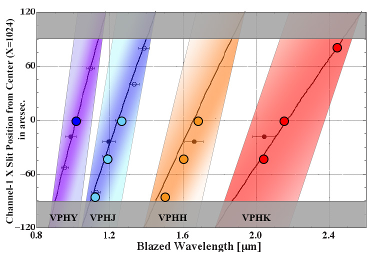
Figure 4: The efficiency peak wavelength (Brazed Wavelength: horizontal axis) as a function of the X slit coordinates (in the RAW Image Coordinates: vertical axis) for channel-1 (solid lines: for VPHY, VPHJ, VPHH, and VPHK from left to right). This is revised from Figure 4 of Ebizuka et al. (2011). The vertical axis indicates the relative position from the center of the detector (X=1024). The same relation holds for channel-2 too, though the sign will be the opposite (negative offset goes for longer blazed wavelengths). Large filled circles are the actual peak position measured in 2016. The hatched region indicates the observable wavelength range for each grism: purple, blue, orange, & red region each indicates the range for VPH-Y, VPH-J, VPH-H, and VPH-K, respectively. Note that the region shown here is defined by the detector edge only: the actual spectra may not extend so due to the peaky efficiency curve. For example, the FWHM of the efficiency curve for VPH-H is roughly 0.15 um (see Fig. 2a), only half of the width of the pink region here. Users should be careful about the effective wavelength coverage usable for observation. We also note that we cannot locate the slit less than -90 arcsec or more than 95 arcsec due to the constraint for the design area (gray-shaded areas).
The wmdp Design
The above characteristics significantly limit the application of the VPH grisms for the MOS observation, because the target position virtually defines the observable wavelength range with high efficiency. The mask design will be complicated if the targets are scattered across the field of view. You will first have to consider the peak wavelength of the grisms at each target position, and then have to find out the targets that have a good match between the spectral feature of your interest and the peak efficiency.
Unfortunately, it is currently impossible to display the peak and the observable spectral range effectively by wmdp_moircs.sav, the MOIRCS mask design software. Therefore, the observatory cannot support the design of the VPHs by the wmdp software. Those who go to observation must manage the design by themselves.
Please use the wmdp_moircs.sav only for putting slits on the target and generating .sbr file. Note that you can change the spectral parameters manually by the menu ("Option" -> "Grism Parameter Setting") so you can make mimicked spectra of VPH. See section 3.7.4 of the manual.
The Observation
We can achieve the background-noise limited observation for the VPH grisms for normal slit width case within reasonable exposure times (<15 min per exposure) with 16-25 times multi-sampling CDS readout.
A challenge related to the MOS observation by VPH would be the observation of the standard stars. A spectrum by the VPH grism basically covers the entire span of the detector in the dispersion direction. Thus the starting and the ending wavelength of the spectra will change from slit to slit (by the slit position) in the MOS data. So, the standard star data by a single representative slit (as we do for R500 grism) does not always work for other slits that are widely separated (in dispersion direction) from it. Thus we need to take the standard star data at a few positions to ensure the whole wavelength coverage.
But, observing a standard star on several slits takes a long time, as we have to do the alignment at each slit. Doing the alignment by removing MOS mask for each slit position is not practical. We try to do this without removing MOS mask if possible. But unfortunately, it does not always work.
As a compromise, we sometimes take standard star data by the slitless observation: we put the star at the slit position with the minimum (, middle), and the maximum X coordinates. A drawback of this is that it will make the resolution of the standard star data the seeing limited, and therefore the data will inevitably have a different resolution from the science data. And also, the standard star should be fairly isolated: unless otherwise the blending could ruin the data.
If you don't need the calibration across the whole wavelength region of the spectra (e.g., emission-line measurement etc), these challenges can be greatly reduced. It is important to tell the SA about your intention on the data to avoid unnecessary overhead by standard star observation.
Your feedback is greatly appreciated.
The Old VPH Information Page (before 2016)
We keep the old VPH information website before 2016 just for the record. Click here.
Any questions should be directed to the Support Astronomer (Ichi Tanaka: ichi$naoj.org [change $ to @]).
Updated on July 29, 2024