IRCS Imaging Information
Optical layout of IRCS camera section
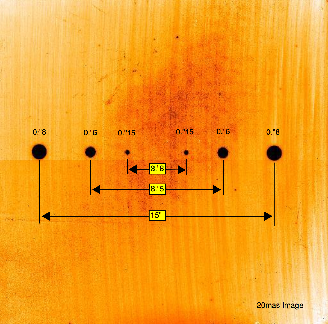
Coronagraph mask
Three mask pairs (0.8'', 0.6'', and 0.15'') are available with different distances between the pair for dithering.
IRCS+AO188 distortion maps (Oct. 2008 - Aug. 2013)
Please see this page.
Bad pixels
Please see the file below for bad pixel information.
- ascii format: cam_badpix.coo
- pixel list format: cam_badpix.pl
Image anomalies
Latency
In common with all ALADDIN arrays, there is some latency. For the current IRCS camera array, latent images are seen at the level of ~0.1% if the wells have been more than half-filled. For this reason, it is recommended to keep your counts well below the saturation level.
Ghost
Beamsplitter and compensator
Note: The beamsplitter and compensator are removed during upgrade work (July 2005 - Jan. 2006). There thus are no ghosts by them since Jan. 2006.
Some ghosting has been observed on IRCS frames. Ghost images are seen in locations 16.9'' north and west of bright sources, with a relative brightness of ~0.3%.
The beamsplitter transmits near-infrared light to the instrument, while reflecting optical light so that it can be fed into the Adaptive Optics system. The compensator is inserted behind the beamsplitter to correct for astigmatism.
Neutral density filter (CaF2)
23 mas pixel scale
58 mas pixel scale