FOCAS new CCDs
(7/31/2010)
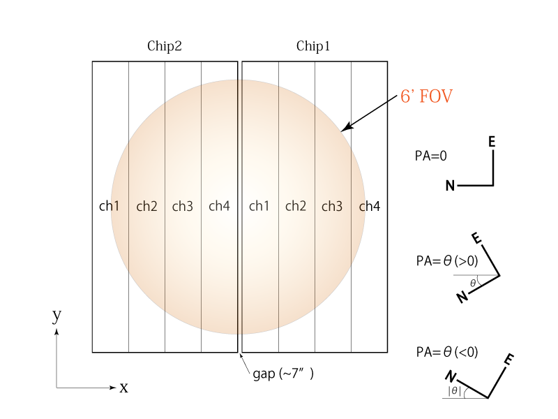
FOCAS uses two fully-depleted-type 2Kx4K CCDs manufactured by Hamamatsu Photonics K.K. Each CCD has four readout channels and each channel has 512x4176 active pixels. The drawing below shows the geometry of the CCDs and channels.
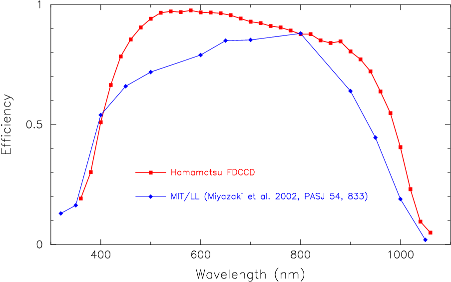
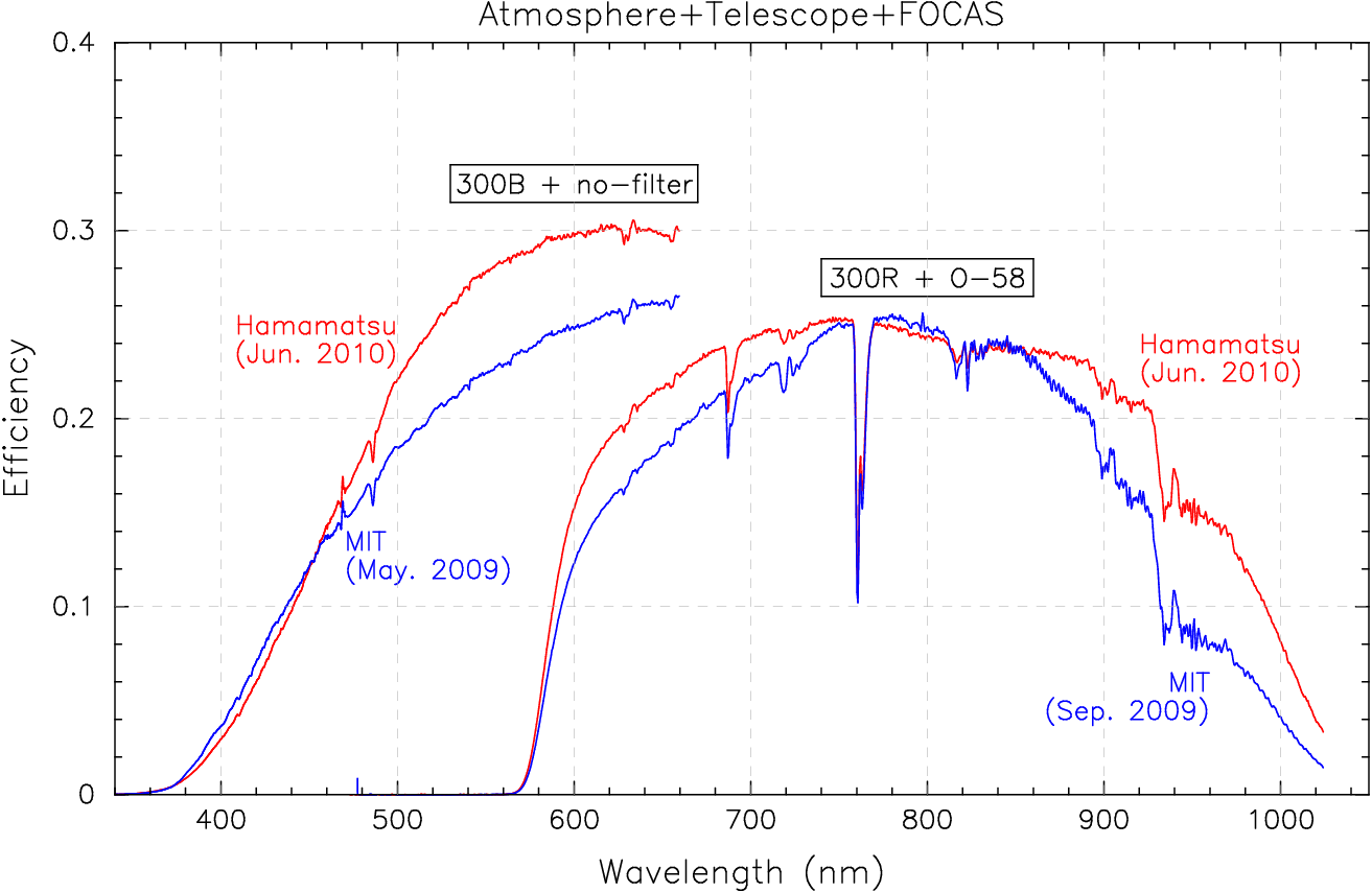
Efficiency (updated 9/28/2010)
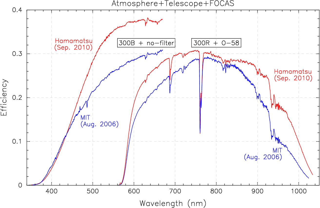
The improvement of the total (atmosphere+telescope+instrument) efficiency is consistent with the CCD QE measurements. The data in the above plot were obtained just after re-aluminizations of the primary mirror in 2006 and 2010. Note that the efficiency measured in June 2010 was lower at least partly because of the condition of the primary mirror.
Characteristics of each channel (updated 9/28/2010)
| Chip2 | Chip1 | |||||||
|---|---|---|---|---|---|---|---|---|
| ch1 | ch2 | ch3 | ch4 | ch1 | ch2 | ch3 | ch4 | |
| gain (e/ADU) | 2.105 | 1.968 | 1.999 | 1.918 | 2.081 | 2.047 | 2.111 | 2.087 |
| readout noise (e) | 4.3(*1) | 3.7 | 3.4 | 3.6 | 4.2(*1) | 3.8 | 3.6 | 4.0 |
| active area(*2) | [9:520,49:4224] | [553:1064,49:4224] | [1081:1592,49:4224] | [1625:2136,49:4224] | [9:520,49:4224] | [553:1064,49:4224] | [1081:1592,49:4224] | [1626:2137,49:4224](*3) |
| over-scan region(*2) | [521:536,*] | [537:552,*] | [1593:1608,*] | [1609:1624,*] | [521:536,*] | [537:552,*] | [1593:1608,*] | [1610:1625,](3) |
(*1) Modification of grounding cables has reduced the readout noise of ch1.
(*2) These values are for images without binning.
(*3) There is an extra column at x=1609 of Chip1 which causes a shift in the position of ch4.
Readout time
| Binning(*1) (spatial x spectral) | Readout time (s) | Image size | Overhead time including readout, wipe, file-transfer, etc. (s) |
|---|---|---|---|
| 1 x 1 | 24 | 2144 x 4241 | ~36 |
| 2 x 1 | 13 | 1104 x 4241 | ~23 |
| 2 x 2 | 7 | 1104 x 2129 | ~17 |
(*1) Because each channel has 512x4176 pixels, readout with 3-pixels binning along X is not recommended.
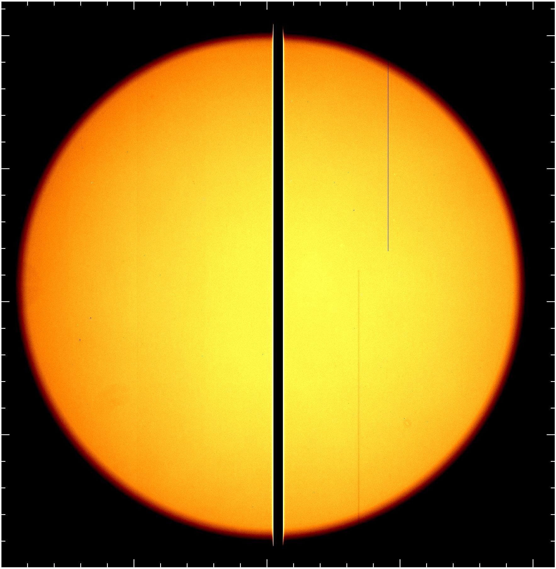
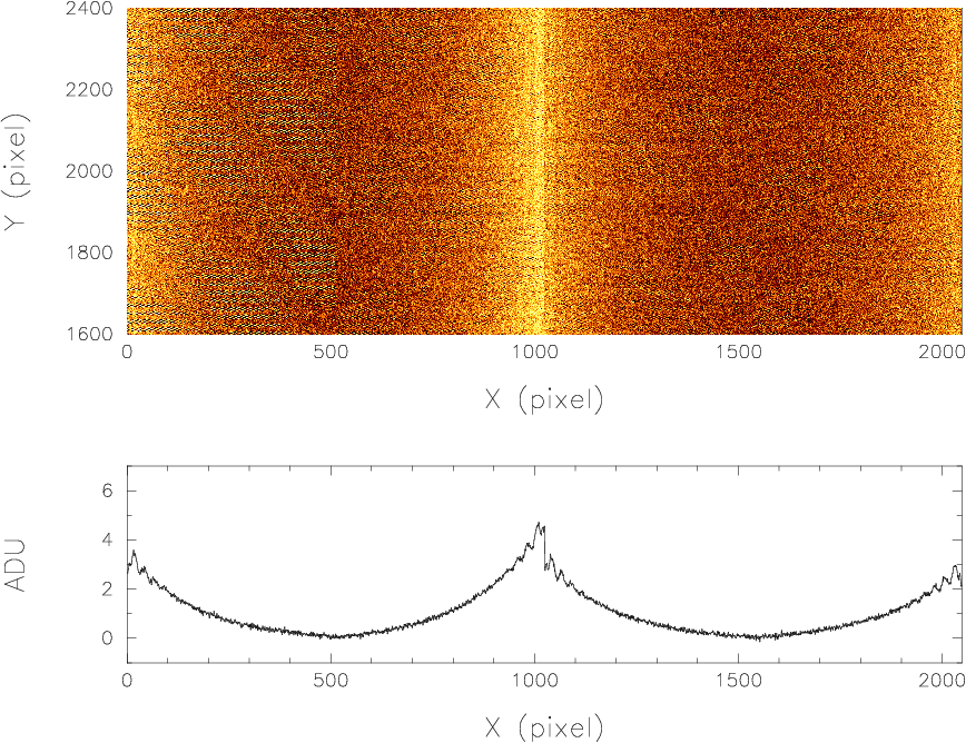
Bias pattern
The following is a bias image of Chip2 after subtracting over-scan region. This pattern should be removed by using bias frames taken at the time of observation.
Cosmetics
Below is a domeflat image in R-band.
① is a dead column in Chip1 located at [833,2387:4241] (no binning, before removing overscan regions).
A vertical line (②) at the lower left of the dead column ([611:613,1:2245]) can be removed by flat-fielding.
(click for larger image)