|
Show content only (no menu, header)
Summary
A coronagraph design for a centrally obscured 2.4m space telescope is presented. The coronagraph architecture, based on the PIAACMC concept, is optimized for low inner working angle (IWA) and high efficiency.
PIAACMC principle
Phase-Induced Amplitude Apodization (PIAA) uses aspheric optics to reshape the telescope beam in an apodized (brighter at the center, fainter at the edges) beam, without loosing light: it therefore preserves the sensitivity and angular resolution of the telescope. Apodized beams are very helpful in coronagraphy, as the telescope's point spread function (PSF) diffraction rings are due to the sharp edges of the unapodized telescope beam.
The PIAA technique can be used by itself to apodize the telescope pupil sufficiently until diffraction
The PIAA concept has evolved towards higher performance and more practical implementation since it was first suggested. The original PIAA concept relied entirely on the aspheric mirrors to perform the beam apodization. In this pure PIAA imager concept, the aspheric optics shapes are well beyond manufacturing capabilities and chromatic propagation effects limit the achievable contrast to 1e-5 in broadband light. These issues were later solved by sharing the apodization with a conventional apodizer, while maintaining quasi full throughput. The resulting PIAA + pupil apodizer hybrid configuration has been adopted for all past and current laboratory demonstrations of PIAA as well as previous mission concept studies using PIAA coronagraphs. By combining the original PIAA coronagraph concept with other coronagraph concepts, is it possible to simultaneously increase performance and make the aspheric PIAA optics easier to manufacture as starlight suppression is shared between components. Recent work has shown that the lossless apodization performed by PIAA is a good match to the apodized pupil Lyot coronagraph (APLC) concept, and a PIAA/APLC hybrid is a particularly powerful combination, allowing 1.3 λ/D inner working angle at 1e-10 contrast with PIAA optics that are easier to manufacture than in previous concepts. The PIAA complex mask coronagraph (PIAACMC), by using a phase-shifting focal plane mask, can further improve performance and theoretically yield a 0.64 λ/D inner working angle, a performance level which cannot be reached on most targets due to finite stellar angular size.
In the PIAACMC architecture adopted, the focal plane mask is a key element which must create a destructive interference within the open areas of the geometrical pupil in the Lyot plane (Fig. 4, left). This requires careful control of both phase and amplitude as a function of wavelength. We will achieve this with a multi-zone reflective focal plane, which is made of silicon, following successful proven manufacturing capabilities at JPL's micro devices laboratory (MDL)
 |
Phase Induced Amplitude Apodization (PIAACMC) principle, shown here for the AFTA pupil in monochromatic light. The pupil (P) is first apodized into a generalized prolate function (A) using lossless PIAA optics and an optional conventional apodizer. A partially transmissive phase-shifting focal plane mask is then used (B) to produce in the output pupil (C) a destructive interference. A Lyot mask then rejects all starlight while offering full throughput for off-axis sources. The inverse PIAA optics recover a sharp off-axis image over a reasonably wide field of view.
|
The PIAA technique is applicable to a wide range of mission size and science goals. For example, a 0.7-meter telescope (EXCEDE [7] mission concept) can image dust disks around nearby stars. A 1.4-meter telescope (PECO mission concept study [8]) can image Earth-like and Super-Earth planets around a sample of 20 nearby stars [9]. On-board a flagship 4-m or larger space telescope, a PIAA would allow measurement of atmospheric composition in nearby Earth-like planets, and permit the identification of bio-markers suggestive of biological activity.
Design and model details
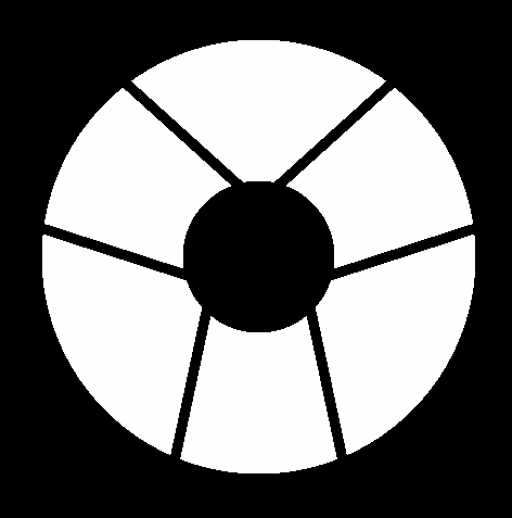
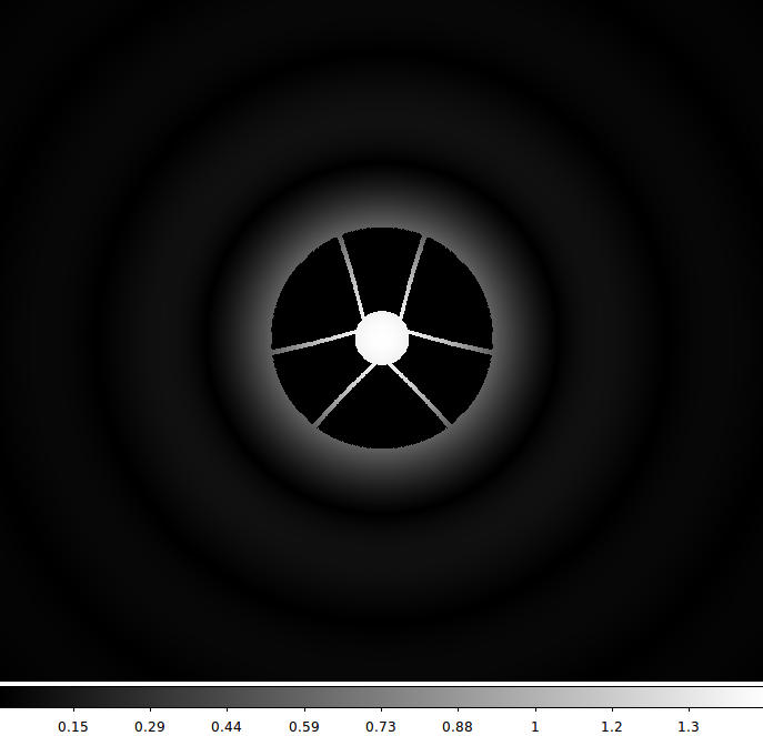
1. Telescope pupil
2. Conceptual monochromatic PIAACMC design
Design parameters (see PIAACMC paper for explanation) : b/2 = 0.9, a/2 = 0.925.
The pupil is first apodized using remapping PIAA optics.
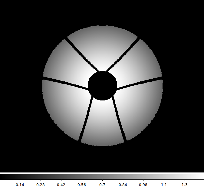
2.1. PIAA apodization
The pupil first goes through PIAA optics. The PIAA optics used here were designed to transform an unobstructed beam into a prolate spheroidal beam.
PIAAapo_amp.prof: amplitude profile (sampled on 200 points) used to design the PIAA optics. If an unobstructed beam were fed into the PIAA optics, this would be the output amplitude (square root of surface brightness) profile. The PIAA apodization is relatively mild, as the center to edge surface brightness ratio is 14.4%, as opposed to 1% for PIAA optics that have previously been made and tested.
The beam remapping is purely radial, and is conveniently described by the following radial remapping (and inverse remapping) tables:
- Mapping function: PIAA_r0r1.txt: output radius (r1) as a function of input radius (r0)
- Inverse mapping function: PIAA_r1r0.txt: input radius (r0) as a function of output radius (r1)
For both tables, unit is : 1 = edge of beam
2.2. Post apodizer
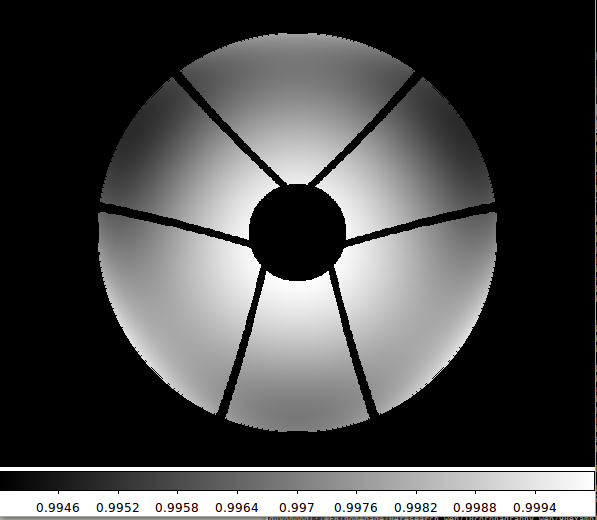 |
Post Apodizer, shown here in amplitude transmission
The post apodizer is a small correction from the circular symmetric apodization profile coming out of the PIAA optics (designed as a radial function for convenience) and the generalized prolate spheroidal apodization function for the AFTA pupil. Note the scale: the darkest parts of this mask have 99% intensity transmission.
compressed FITS file (4096x4096)
|
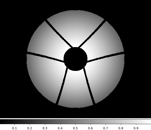
2.3. Total apodization
2.4. Focal plane mask
The focal plane mask has a a/2=0.925 l/D radius. Its complex amplitude is 1 for r > a/2, and -0.4156 for r < a/2 (17% intensity transmission, half wave phase shift).
2.5. Lyot Stop
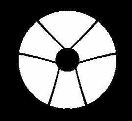 |
Lyot Stop
The Lyot stop is not undersized, so it does not stop any of the light for an off-axis source sufficiently far from the optical axis to not experience the focal plane mask.
compressed FITS file (4096x4096)
|
3. Monochromatic design performance
The PIAACMC achieves total on-axis extinction for an on-axis point source in monochromatic light.
3.1. System throughput
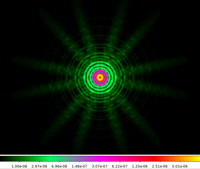
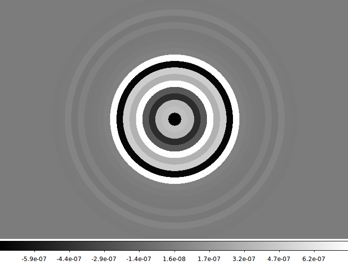
3.2. Sample PSFs
Full system: PIAA + apodizer + focal plane mask + inverse PIAA.
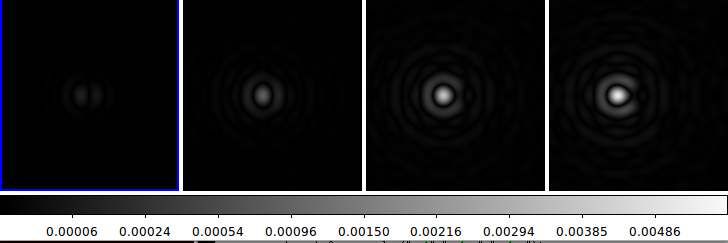 |
Off-axis PSFs
From left to right: 0.2 l/D, 0.5 l/D, 1.0 l/D, 2.0 l/D
|
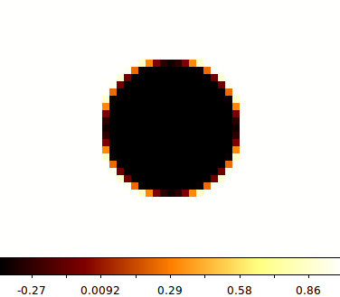
3.3. Sensitivity to stellar angular size
Typical target has 1mas diameter, which is 0.01 l/D diffraction limit radius at 0.6um. Nearby M-type stars, or G-type stars at 10pc have similar angular sizes, so 1mas diameter is a good assumpution.
Simulated response to star diameter = 0.02 l/D (radius = 0.01 l/D): total stellar leak = 2.58e-05
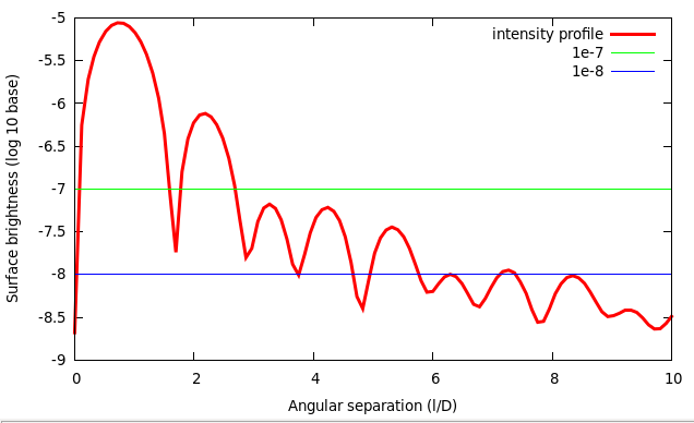 |
PIAACMC image of a 0.01 l/D radius stellar disk: radial profile
ASCII file, pixel scale = 0.097656 l/D per pix
|
Given that the PIAACMC will fundamentally be limited to 1e-6 to 1e-7 raw contrast near its IWA due to stellar angular size, there is little advantage in pushing chromatic errors well below these levels. The next 2 sections show that this can be achieved with masks that can be manufactured with current lithography capabilities, consisting of no more than 20 rings of SiO2.
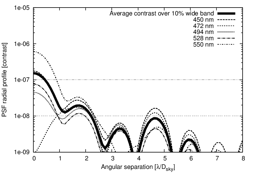
4. Polychromatic design: 10% wide band centered around 0.5 um
For polychromatic operation, the focal plane mask consists of a transmissive SiO2 substrate with concentric rings, each with a different thickness. There are 19 rings in this design, regularly spaced, with the outer edge of the outer ring at 2 l/D radius at the center wavelength (0.5um). In this simulation, it is assumed that there is no WF control and that all optics are perfect.
Routine used to compute SiO2 refractive index
// phase offset as function of mask thickness and lambda
double cfpm_achrom_pha_lambda( double z, double lambda )
{
  double pha;
  double n;

  double nair = 1.0;

  // SiO2
  double SiO2_n0 = 1.28604141;
  double SiO2_B1 = 1.07044083;
  double SiO2_C1 = 1.00585997e-2;
  double SiO2_B2 = 1.10202242;
  double SiO2_C2 = 100.0;

  double lambdaum;

  lambdaum = lambda*1.0e6;


  n = sqrt(SiO2_n0 + (SiO2_B1*lambdaum*lambdaum)/(lambdaum*lambdaum-SiO2_C1) +(SiO2_B2*lambdaum*lambdaum)/(lambdaum*lambdaum-SiO2_C2));

  pha = 2.0*M_PI * (n-nair)*z / lambda;

  return(pha);
}
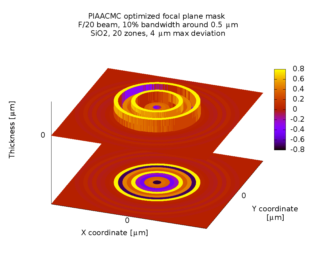 |
Focal plane mask 3D view
|
System performance for on-axis point source (contrast values averaged from 0.9 to 3.6 l/D radius):
ON-AXIS TOTAL FLUX = 5.731666e-07
00  Lambda = 0475.00 nm   Average contrast = 8.357860e-09
01  Lambda = 0480.56 nm   Average contrast = 6.815973e-09
02  Lambda = 0486.11 nm   Average contrast = 5.462926e-09
03  Lambda = 0491.67 nm   Average contrast = 5.040837e-09
04  Lambda = 0497.22 nm   Average contrast = 4.748327e-09
05  Lambda = 0502.78 nm   Average contrast = 5.073277e-09
06  Lambda = 0508.33 nm   Average contrast = 5.373980e-09
07  Lambda = 0513.89 nm   Average contrast = 3.192430e-09
08  Lambda = 0519.44 nm   Average contrast = 2.649591e-09
09  Lambda = 0525.00 nm   Average contrast = 8.426986e-09
OVERALL AVERAGE CONTRAST = 5.194418e-09
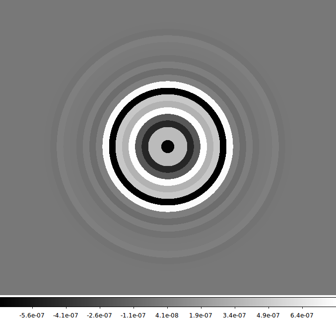
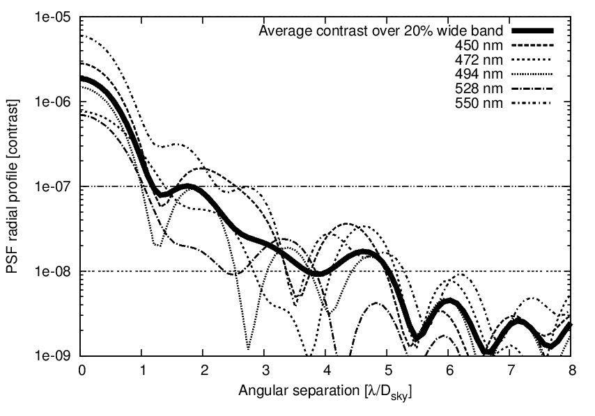
5. Polychromatic design: 20% wide band centered around 0.5 um
System performance for on-axis point source (contrast values averaged from 0.9 to 3.6 l/D radius):
ON-AXIS TOTAL FLUX = 3.168253e-06
00  Lambda = 0450.00 nm   Average contrast = 6.331186e-08
01  Lambda = 0461.11 nm   Average contrast = 2.270459e-08
02  Lambda = 0472.22 nm   Average contrast = 2.537368e-08
03  Lambda = 0483.33 nm   Average contrast = 2.376486e-08
04  Lambda = 0494.44 nm   Average contrast = 2.041708e-08
05  Lambda = 0505.56 nm   Average contrast = 3.021031e-08
06  Lambda = 0516.67 nm   Average contrast = 3.405070e-08
07  Lambda = 0527.78 nm   Average contrast = 1.523218e-08
08  Lambda = 0538.89 nm   Average contrast = 1.046652e-08
09  Lambda = 0550.00 nm   Average contrast = 9.108467e-08
OVERALL AVERAGE CONTRAST = 2.882424e-08
Page content last updated:
27/06/2023 06:35:52 HST
html file generated 27/06/2023 06:34:38 HST
|