High performance coronagraphy on unfriendly apertures

High performance coronagraphy on unfriendly apertures |
|
Home |
Show content only (no menu, header)High Performance Lyot and PIAA Coronagraphy for Arbitrarily shaped AperturesSummaryTwo high performance coronagraphic approaches compatible with any pupil shape are described. Both concepts use entrance pupil amplitude apodization and a combined phase and amplitude circular focal plane mask to achieve full coronagraphic extinction of an on-axis point source. While the fist concept, named Apodized Pupil Complex Mask Lyot Coronagraph (APCMLC), relies on a transmission mask to perform the pupil apodization, the second concept, named Phase-Induced Amplitude Apodization complex mask coronagraph (PIAACMC), uses beam remapping for lossless apodization. Both concepts offer complete coronagraphic extinction (no limit in contrast) of a point source, with high throughput and sub-λ/D inner working angle, regardless of aperture shape. The PIAACMC offers nearly 100% throughput and approaches the fundamental coronagraph performance limit imposed by first principles. Both coronagraphs can also be designed for IWA larger than λ/D if performance requirements should be relaxed to improve robustness to pointing error, stellar angular size or chromaticity. For the PIAACMC, the large-IWA designs maintain full throughput and total on-axis extinction, thus offering practical high performance coronagraphic options. The steps toward designing the coronagraphs for arbitrary apertures are described. Designs for the APCMLC and the higher performance PIAACMC are shown for several monolith and segmented apertures, such as the apertures of the Subaru Telescope, Giant Magellan Telescope (GMT), Thirty Meter Telescope (TMT), and European Extremely Large Telescope (E-ELT).1. IntroductionDirect imaging of exoplanets with ground-based telescopes is becoming possible thanks to advances in adaptive optics, as demonstrated by several recent direct imaging exoplanet discoveries [Lagrange et al. 2010] [Marois et al. 2009]. While current ground-based instruments are most sensitive to relatively massive and young planets at large angular separation (beyond a few tenths of arcsec), recent developments in coronagraphic techniques, extreme Adaptive Optics and calibration techniques are pushing detection limits deeper in contrast and closer in angular separation, soon providing access to the planet-rich inner parts of planetary systems [Macintosh et al. 2008] [Beuzit et al. 2008] [Martinache & Guyon 2009][Crepp et al. 2011]. Direct imaging of the inner part (1 to 5 AU) of young planetary systems is of especially high scientific value to constrain and understand planetary systems formation and evolution near the habitable zone, and requires the combination of an efficient coronagraph offering small inner working angle and a high level of wavefront correction and calibration. High contrast imaging from space allows access to considerably better contrast than possible with ground-based telescopes, thanks to the absence of atmospheric turbulence. Laboratory coronagraphy systems have demonstrated that raw contrasts of about 1e-9 can be achieved in a stable environment with a deformable mirror and a coronagraph [Trauger & Traub 2007]. At such high contrast, coronagraphic imaging can allow characterization of potentially habitable planets through spectroscopy from space [Levine et al. 2009]. While most high performance coronagraphs are designed for unobstructed circular pupils, current and future large ground-based telescopes are centrally obscured, and also segmented above 8.4-m diameter. Future large space-based telescopes will also likely be centrally obscured and/or segmented, although a telescope dedicated to high contrast imaging could be build off-axis if required for coronagraphy [Levine et al. 2009]. The scientific return of an exoplanet direct imaging mission or instrument is a steep function of telescope diameter: larger telescopes allow access to exoplanets at smaller angular separations, which are brighter in reflected light (apparent luminosity scales as inverse square of angular separation in reflected light), more numerous (the number of planets of a given type accessible with a telescope scales as the third power of telescope diameter), and more relevant to exoplanet systems habitability than widely separated planets. Larger ground-based telescope size also allows higher contrast observation by better concentrating planet light over the speckle halo background, and the gain in collecting area enables spectroscopic characterization. It is therefore essential to identify and develop coronagraph concepts which can deliver high performance on centrally obscured and/or segmented apertures. Coronagraph designs for centrally obscured and/or segmented apertures have been proposed by several authors, offering a range of solutions and approaches as diverse as coronagraph concepts are:
A different approach to this problem is to remap the entrance aperture to remove central obstruction and/or spiders. [Murakami & Baba 2005] propose a 2-mirror system to remove central obstruction and spiders for a four-quadrant coronagraph. [Guyon & Shao 2006] propose a high efficiency nulling coronagraph concept adapted to central obstruction and spiders by performing destructive interferences between pairs of unobstructed off-axis subapertures. [Lozi et al. 2009] demonstrate that a prism-like transmissive device and aspheric optics can be used to remove both central obstruction and spiders from the Subaru Telescope pupil, theoretically allowing high performance coronagraphy with the full telescope aperture. These remapping solutions are complex, challenging to implement and align, and extremely sensitive to tip-tilt and stellar angular size at high contrast: when points on either size of an obstruction are brought next to each other in the remapped pupil, a small tip-tilt in the entrance beam leads to a phase discontinuity in the remapped beam. When due to finite stellar angular diameters, diffraction due to this discontinuity cannot be mitigated or controlled by wavefront control, as it is incoherent (opposite sides of the stellar disk produce diffracted light components of opposite signs). [Serabyn et al. 2007] choose to avoid entirely the problem by using an unobstructed 1.5-m diameter off-axis part of the 5-m Palomar telescope to perform high contrast imaging with the optical vortex coronagraph. While this allows the use of high performance coronagraphs designed for unobstructed apertures, the performance loss due to the use of an aperture considerably smaller than the full telescope is significant. The solutions previously proposed to mitigate the effects of central obstruction, spiders and gaps are generally suitable for ground-based coronagraphy at a few λ/D IWA, with a raw contrast around 1e-5, as reported by [Martinez et al. 2008] who performed a study of coronagraphic performance on ELTs including realistic assumptions on the level of residual wavefront error after an extreme-AO system. For most of the coronagraphs, central obstruction and spiders were found to have a major impact on performance, limiting the achievable contrast to 1e-4 in the 1 to 4 λ/D separation range. The notable exceptions to this rule were the AIC, which is insensitive to centro-symmetric pupil features (such as a central obstruction or a set of four radial spiders at 90 deg), and the APLC, which could be designed to take into account central obstruction and was found to be quite robust to spiders at the 1e-5 contrast level. The coronagraphs concepts for which ground-based designs compatible with central obscuration have been proposed (shaped aperture, APLC, band-limited Lyot coronagraph) are unfortunately not able to offer IWA less than ~2 λ/D, therefore precluding the observation of most reflected-light exoplanets with EELTs. The solutions previously proposed also do not enable high contrast coronagraphy on centrally obscured or segmented apertures. In this paper, high contrast coronagraphy is defined as reaching ~1e-9 contrast with an IWA of ~3 λ/D or less, as required for space-based direct imaging and spectroscopic characterization of Earth-like exoplanets. The work presented in this paper is aimed at demonstrating that high performance coronagraphy is possible on centrally obscured and/or segmented pupils for both ground-based and space-based telescopes. The Apodized Pupil Complex Mask Lyot Coronagraph (APCMLC) and Phase-Induced Amplitude Apodization complex mask coronagraph (PIAACMC) concept, previously described for circular unobstructed apertures in Guyon et al. 2011, are here adapted to arbitrarily shaped apertures. Section 2 describes how the APCMLC can be adapted to non-circular apertures, and a step by step process to design a APCMLC for any aperture shape is proposed and examples are shown. In section 3, the PIAACMC is shown to offer performance superior to the APCMLC, and its design for centrally obscured and segmented apertures is discussed, with examples representative of current and future large telescopes shown. 2. Apodized pupil complex mask Lyot Coronagraph (APCMLC) for apertures of arbitrary shape2.1. PrincipleIn this section, it is shown that the APCMLC is compatible with non-circular apertures, as illustrated in figure 1, and a description of how it can be designed for arbitrarily shaped pupils is provided. While the APCMLC description provided here remains qualitative and focused of aspects relevant to non-circular apertures, a more complete analytical description is provided in [Guyon et al. 2010] for circular unobstructed apertures.
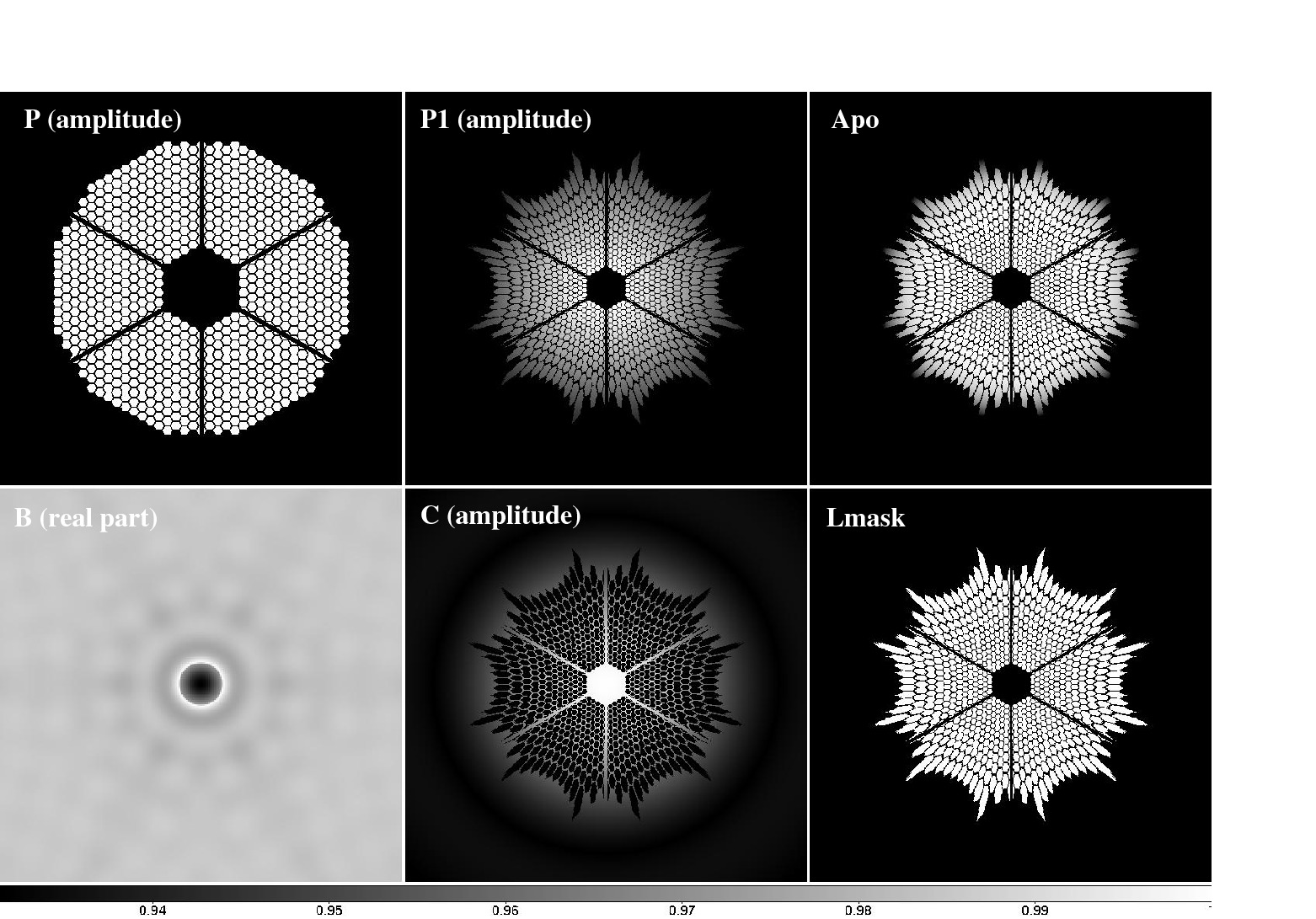
The APCMLC, illustrated in figure 1, uses a circular focal plane mask to partially transmit and phase shift the on-axis point spread function (PSF) core (complex amplitude B on figure 1). This produces a destructive interference within the geometric pupil, between the light that passes around the focal plane mask disk and the phase-shifted light passing through the focal plane phase-shifting disk. With a Lyot mask (Lmask) selecting only the geometric pupil, a coronagraphic effect is achieved. The concept is thus an intermediate point between the conventional Lyot coronagraph or Apodized Pupil Lyot Coronagraph (APLC) [Soummer et al. 2003], which use a large fully opaque focal plane mask, and the phase mask coronagraph [Roddier & Roddier 1997] [Guyon & Roddier 2000] [Guyon et al 1999] [N'diaye et al. 2010] which uses a small size fully transmissive phase-shifting focal plane mask. In the APCMLC, the focal plane mask size can be chosen anywhere between these two extremes, and defines the ratio between the amount of light within the circular mask and outside the mask. As the focal plane mask radius decreases, a smaller fraction of the light is within the mask radius, and its transmission must increase to maintain the flux balance between the "inside focal plane mask" and "outside focal plane mask" components, a necessary condition to achieve destructive interference. Full destructive interference within the geometric pupil also requires that the two components are equal in amplitude for every point within the pupil. Since this match does not naturally occur, all 3 concepts (APLC, Roddier phase mask coronagraph and APCMLC) require the entrance pupil to be amplitude apodized to enforce this match. Qualitatively, for small focal plane mask size, the apodization mostly changes the pupil light distribution for the "outside focal plane mask" component, while the light distribution for the "inside focal plane mask" component is mostly driven by the size of the focal plane mask. The entrance pupil apodization can therefore be iteratively derived to force the "outside focal plane mask" component to match the "inside focal plane mask component", using the following steps:
The APCMLC is described here analytically using notations shown in figure 1. The entrance pupil shape is defined by the real function P(r), with r the 2-D position vector in the pupil plane, and P(r)=1 for points within the pupil and P(r)=0 outside of the pupil. The apodizer function Apo(r) is applied to the pupil, yielding the following complex amplitude in plane A:
The same pupil apodization technique is used in the Apodized Pupil Lyot Coronagraph (APLC) to optimize the pupil entrance complex amplitude to the hard edged opaque focal plane mask [ref Soummer]. In the APLC, t=0 in equation (7), and the coronagraphic extinction is therefore not total for an on-axis point source. Equation (7) shows that the on-axis PSF in the final focal plane mask is an exact copy of the non-coronagraphic PSF, scaled by (1-Λa)2 in intensity. For large focal plane masks diameter a, Λa is close to 1, and the coronagraphic extinction is satisfactory. The APLC concept has been adopted for the Gemini Planet Imaging [ref] and has been validated in laboratory demonstrations [Thomas et al. 2011]. The APCMLC concept is very similar to the APLC, the only fundamental difference being that its focal plane mask transmission is allowed to be non-zero, therefore allowing full coronagraphic extinction for any focal plane mask size a for which Λa > 0.5. 2.2. APCMLC designs for segmented aperturesApodized pupil complex mask Lyot coronagraphs (APCMLCs) were designed for the Subaru Telescope, GMT, TMT and E-ELT pupil geometries, following the process described in the previous section. For each pupil geometry, several focal plane mask sizes were chosen. The designs with the smallest possible focal plane mask sizes use full transmission π-phase shifting circular focal plane masks, and are referred to as optimal IWA APCMLC designs in this paper. As the focal plane mask size increases, it also becomes more opaque, the system throughput (which is equal to the apodizer throughput) decreases and the IWA increases. Results are summarized in table 1, and show that optimal IWA designs offer IWAs around 0.9 λ/D and throughputs around 60%. For all designs, the IWA is approximately equal to the focal plane mask radius, and the throughput decreases rapidly with increasing focal plane mask size: with a 1.2 λ/D radius, the throughput ranges from approximately 10% to 35% depending on the pupil geometry. The performance of the optimal IWA design is largely independent of pupil geometry, and is similar for segmented apertures to the performance previously reported [ref] for a full unobstructed circular pupil. However, as the mask size increases, pupil geometry has a larger impact on performance, as the range of pupil plane spatial frequencies accessed by the focal plane mask begins to overlap with the low spatial frequency components of the pupil geometry (central obstruction, large segments, thick spider vanes). This difference is most noticeable between the GMT pupil with few large segments and the TMT or EELT geometries with numerous small segments.
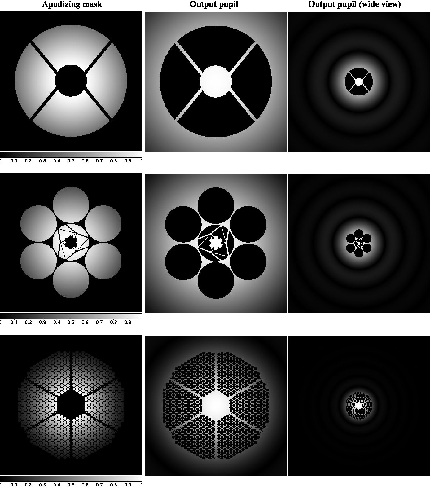
Selected examples of apodization functions and Lyot plane intensity images are shown in figure 2. In each case, the apodization function is smooth and free of high spatial frequencies, and no light is left within the geometric pupil in the Lyot pupil plane, as all residual starlight is diffracted outside of the pupil and in the gaps between segments. The examples chosen in this figure show how the diffracted light in the output pupil plane becomes more concentrated around the pupil as the focal plane mask size increases.
Transmission curves are given in figure 3 for the APCMLC designs listed in table 1. 3. Phase Induced Amplitude Apodization Complex Mask Coronagraph (PIAACMC) for apertures of arbitrary shape3.1. Lossless Phase-Induced Amplitude Apodization (PIAA)While the APCMLC described in section 2 achieves full on-axis coronagraphic extinction for almost any pupil shape, its throughput is limited by the entrance apodization required to achieve perfect destructive interference in the output pupil plane. The system throughput decreases as the focal plane mask size increases, with a maximum throughput equal to 72% for a 0.64 λ/D radius purely phase-shifting transparent mask on a circular unobstructed aperture. Throughput, and consequently angular resolution, degrade rapidly with increased focal plane mask size: it is 18% for a 2 λ/D radius mask. The results obtained in Section 2.2 also show that the APCMLC maximum throughput (achieved for the designs with the most aggressive IWA) is lower on segmented pupils than it is for an unobstructed circular pupil. Moreover, throughput, angular resolution and IWA are significantly degraded when the focal plane mask size is increased - while mitigation of undesired chromatic effects at the focal plane mask may require a larger and more opaque mask. Phase-induced Amplitude Apodization (PIAA) uses aspheric mirrors to achieve a lossless beam apodization [], and can therefore produce a highly apodized beam suitable for high contrast imaging without the angular resolution loss and throughput loss of a conventional apodizer. PIAA can also be used to replace the entrance apodization in the APCMLC design described in section 2.1, as previously proposed for unobstructed circular pupils []. The resulting coronagraph, denoted Phase-induced Amplitude Apodization Complex mask coronagraph (PIAACMC), offers simultaneously full throughput, small inner working angle and total on-axis extinction.
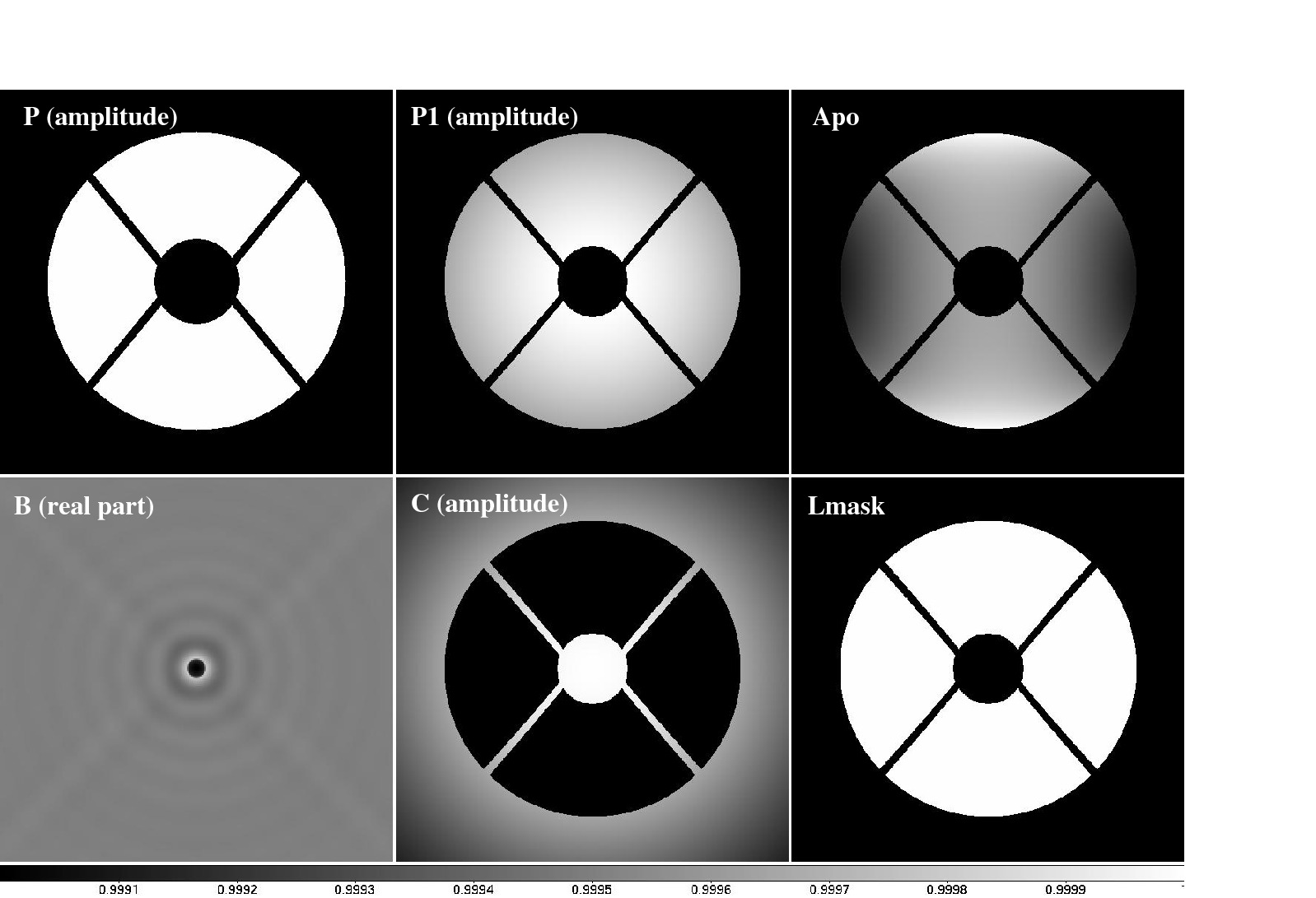
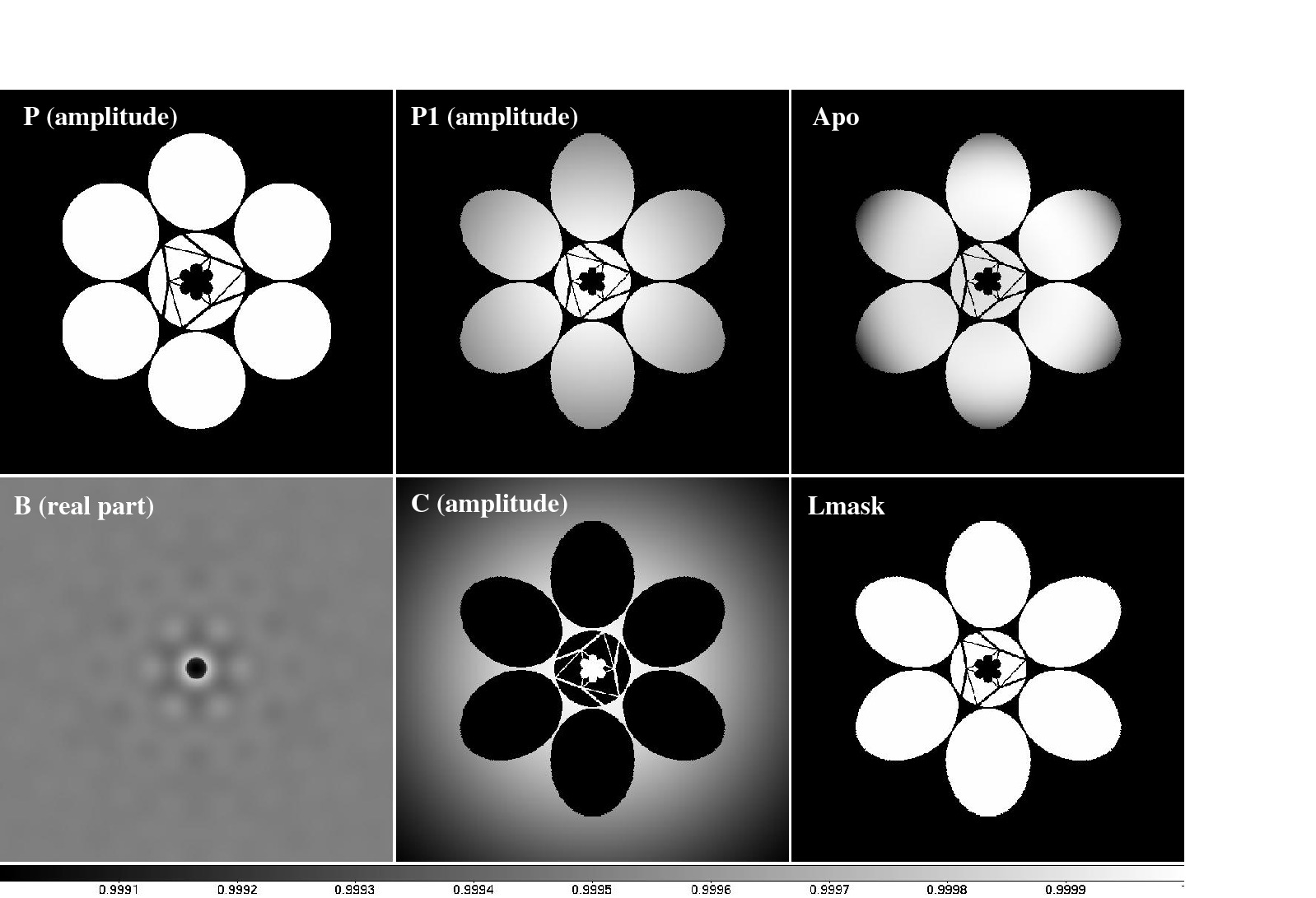
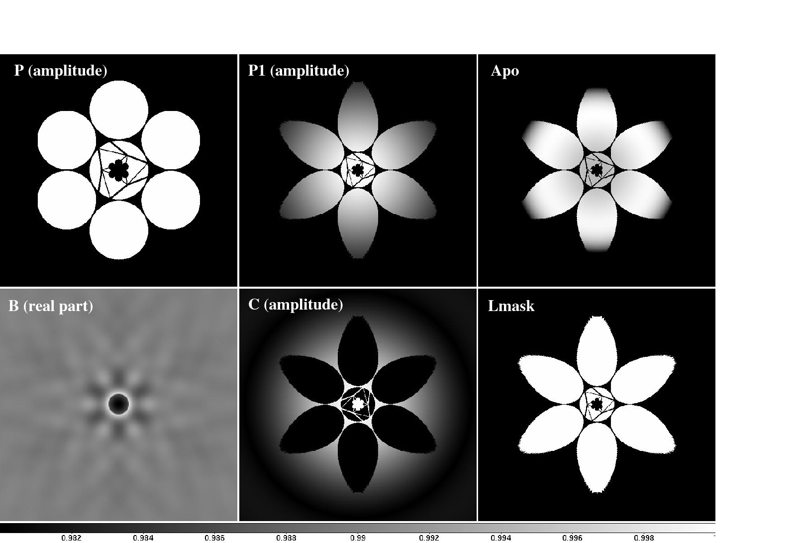
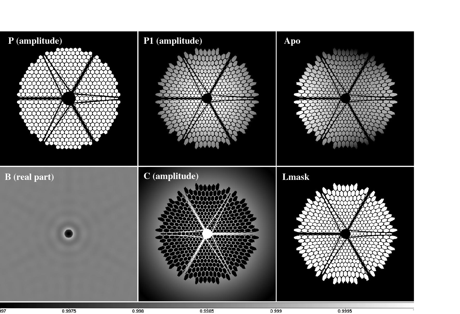
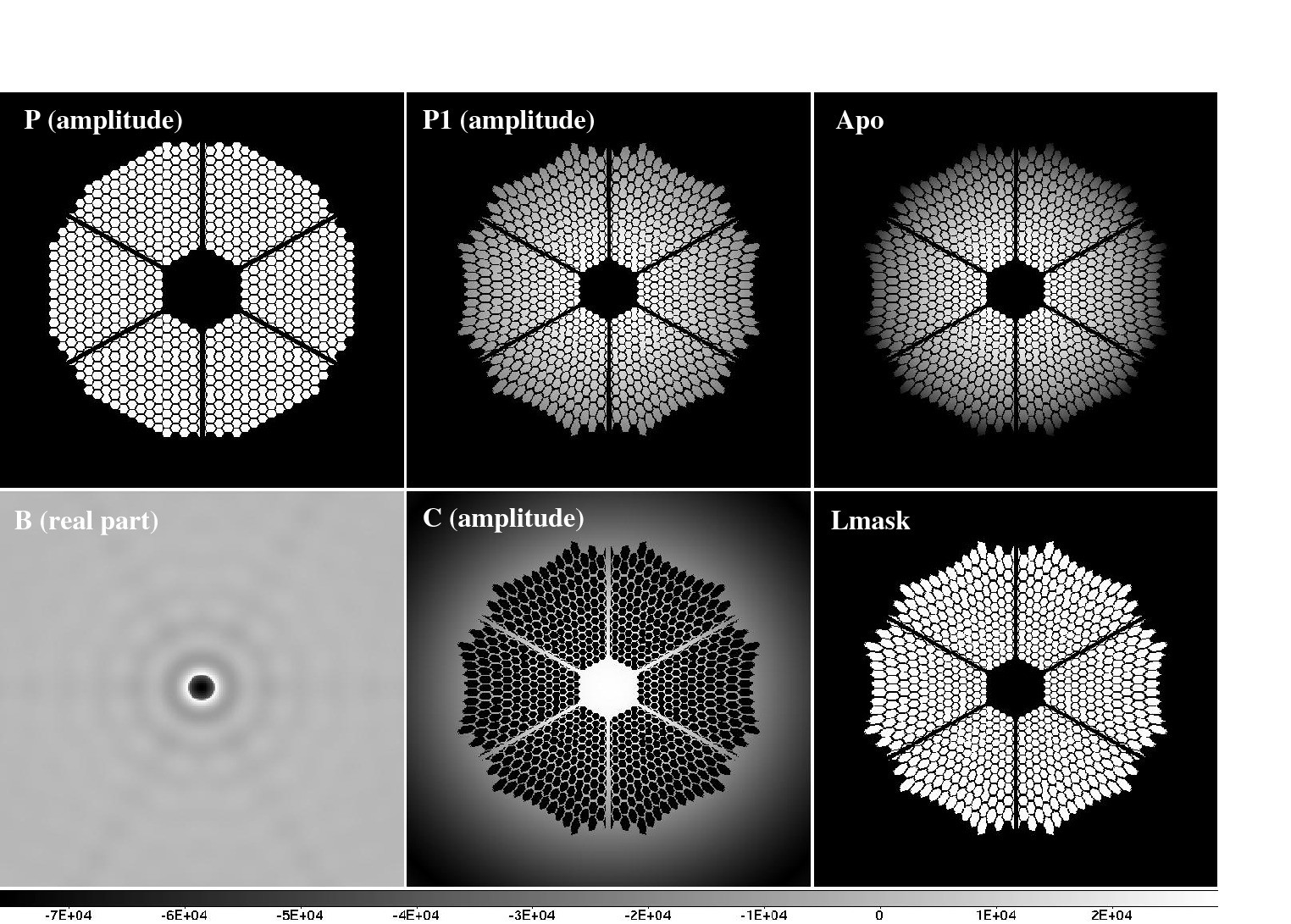
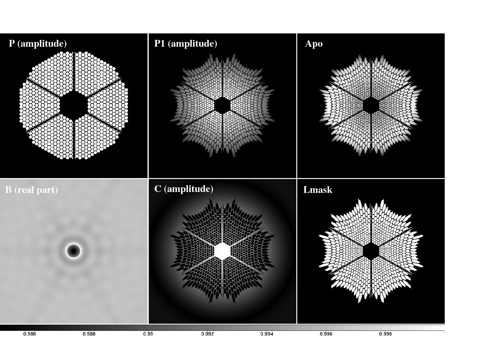
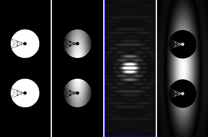
An example PIAACMC design is shown in figure 3 for a segmented centrally obscured pupil. The entrance pupil P (image shown in the lower left of the figure) is apodized with lossless aspheric PIAA optics. Because the PIAA optics perform apodization by remapping instead of selective transmission, the resulting pupil P1 shape is modified. A conventional apodizing mask may be used to fine-tune the apodization if the PIAA optics do not exactly produce the required amplitude distribution (this will be addressed in the following section). The resulting pupil A is shown in the second image from the lower left corner. The image of an on-axis point source is shown in the center image, where the phase-shifting partially transmissive focal plane mask is inserted. In the output pupil plane C, all light within the pupil has been removed, while diffracted starlight fills the gap and obstructions of the segmented pupil. A Lyot mask (noted Lmask) can then select only the geometric pupil area (after remapping) to fully block on-axis starlight while fully transmitting the light from distant off-axis source. A well-documented side-effect of apodization with PIAA optics is that off-axis PSFs are highly distorted, and corrective optics (inverse PIAA) are required at the output of the coronagraph to maintain diffraction limited sharp PSFs over a scientifically useful field of view [ref Lozi]. Except for PIAA and inverse PIAA optics, the PIAACMC architecture is functionally identical to the APCMLC architecture described in section 2.1: between planes P1 (output of the PIAA optics) and the plane immediately after the pupil plane Lyot mask, the architecture is an APCMLC. The main difference between APCMLC and PIAACMC is that the lossless apodization allows increased performance by maintaining full throughput and angular resolution, regardless of the focal plane mask size adopted. 3.2. Designing a PIAACMC for a non circular apertureA PIAACMC is designed by performing a lossless PIAA apodization of the pupil to produce a generalized prolate function for the aperture. In the unobstructed circular pupil case [ref], designing the PIAACMC is relatively simple, as PIAA apodization using a radial remapping function preserves the circular aperture shape. The prolate function can thus be first computed, and then realized with a radial PIAA apodization. Designing a PIAACMC for complex shaped apertures is considerably more challenging because the PIAA apodization modifies the aperture shape, which itself changes the generalized prolate function. In addition to this circular problem, if the aperture is not circularly symetric, the generalized prolate is also not symmetric, and the required remapping function therefore cannot be written as a radial function. While PIAA optics can be designed for any radial remapping [ref], an arbitrarily chosen 2D remapping function can almost never be realized with a set of two PIAA optics. To overcome the two challenges listed above (circular design problem due to effect of PIAA on aperture shape, and complexity/impossibility of designing PIAA optics for non-circular symmetric remapping), a hybrid PIAACMC design is adopted, which includes a conventional apodizer after the remapping to produce the required prolate function. Thanks to this post-apodizer, the output of the PIAA apodization does not need to exactly match the generalized prolate function, allowing radial remapping functions to be used on non-circular symmetric apertures. The goal of the design optimization is to bring the PIAA apodization and generalized prolate functions close, in order to minimize the strength of the post-apodizer and thus maintain a high system throughput. The proposed steps for designing a PIAACMC for complex shaped apertures are :
3.3. PIAACMC design examples3.3.1. Centrally obscured pupils: Subaru Telescope pupilThe Subaru telescope pupil is representative of current large aperture astronomical telescopes, with a large central obstruction and thick spiders. Both features must be taken into account for the design of a high performance coronagraph.
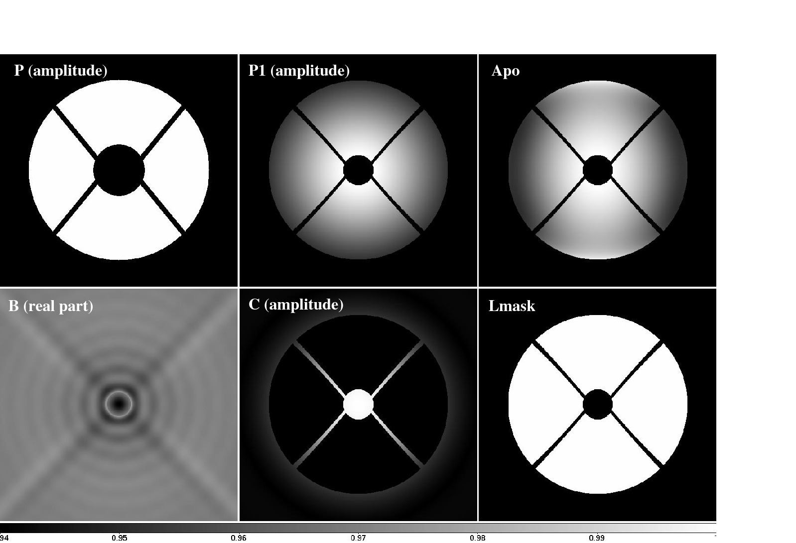
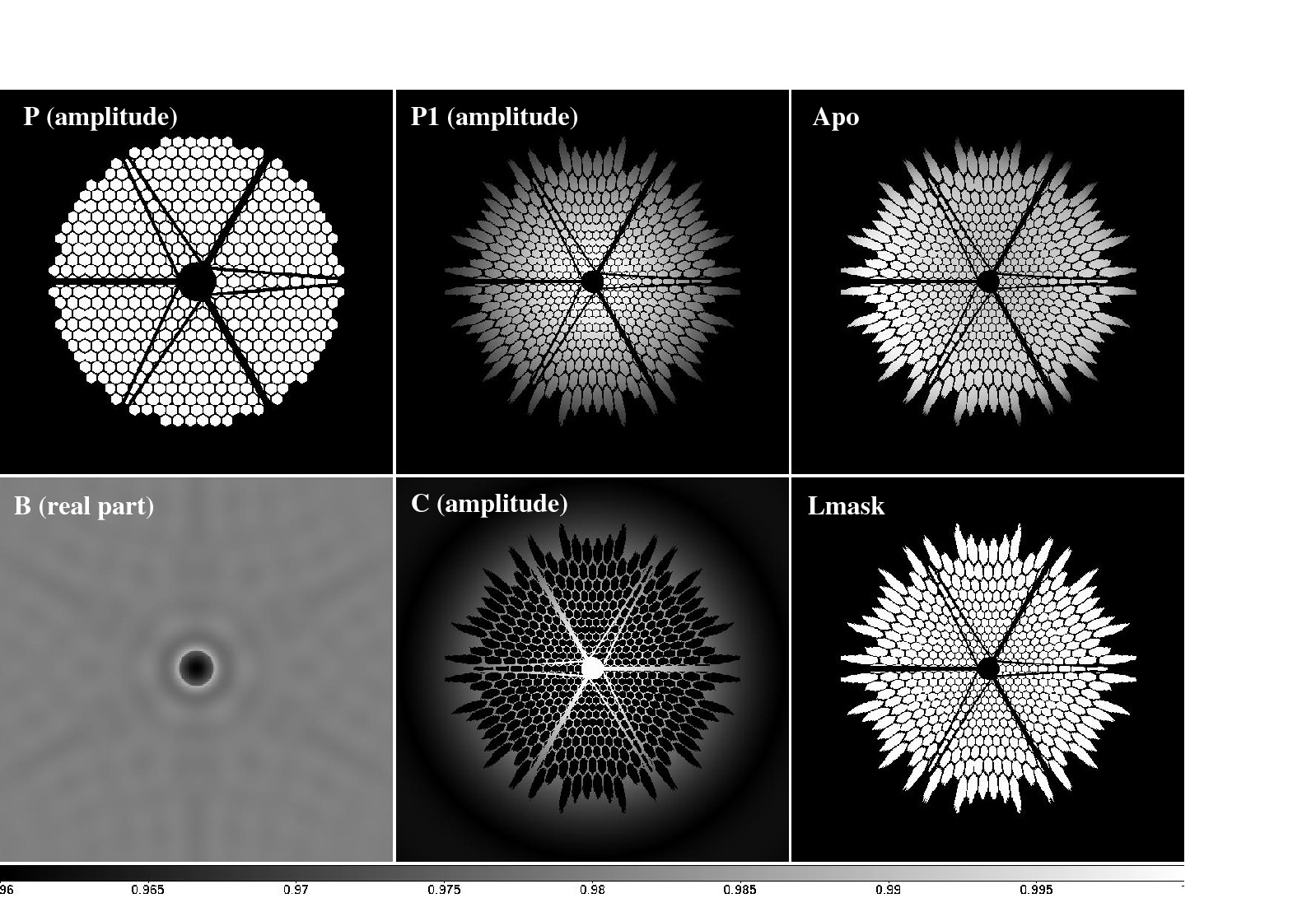
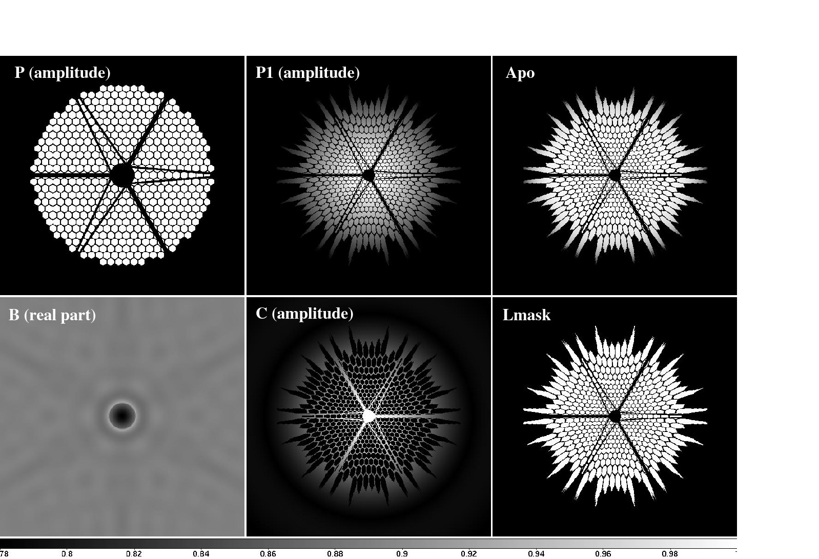
Fig 4 and 5 show two PIAACMC designs for the Subaru Telescope pupil. The small IWA design shown in figure 3.1 was computed from the b/2=0.6 λ/D beam remapping, and uses a small sub-λ/D radius focal plane mask with high transmission. The large IWA design was computed from b/2=1.2λ/D, adopts a larger mostly opaque focal plane mask, and relies on a stronger PIAA remapping. Both designs offer throughput above 97%, and their throughput could be further increased by slightly elongating the focal plane mask, which was kept circular for simplicity in this study. The large IWA design, by relying on a stronger PIAA remapping, introduces a large pupil deformation, as visible in figure 3.2. The post-focal plane mask pupil images demonstrate the PIAACMC's ability to diffract all of the light from a central source outside the geometrical pupil, including within the gaps of the pupil (here, central obstruction and spiders).
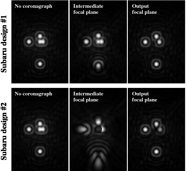
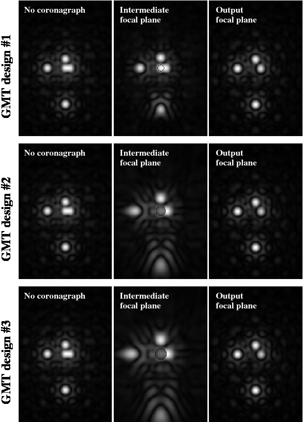
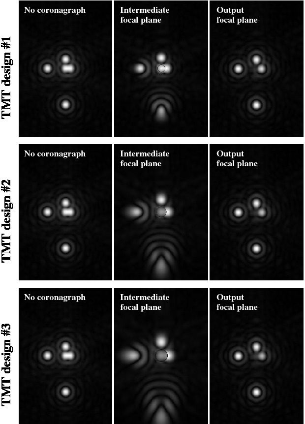
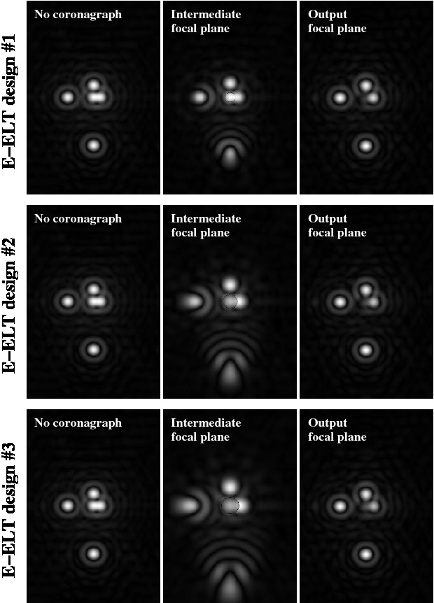
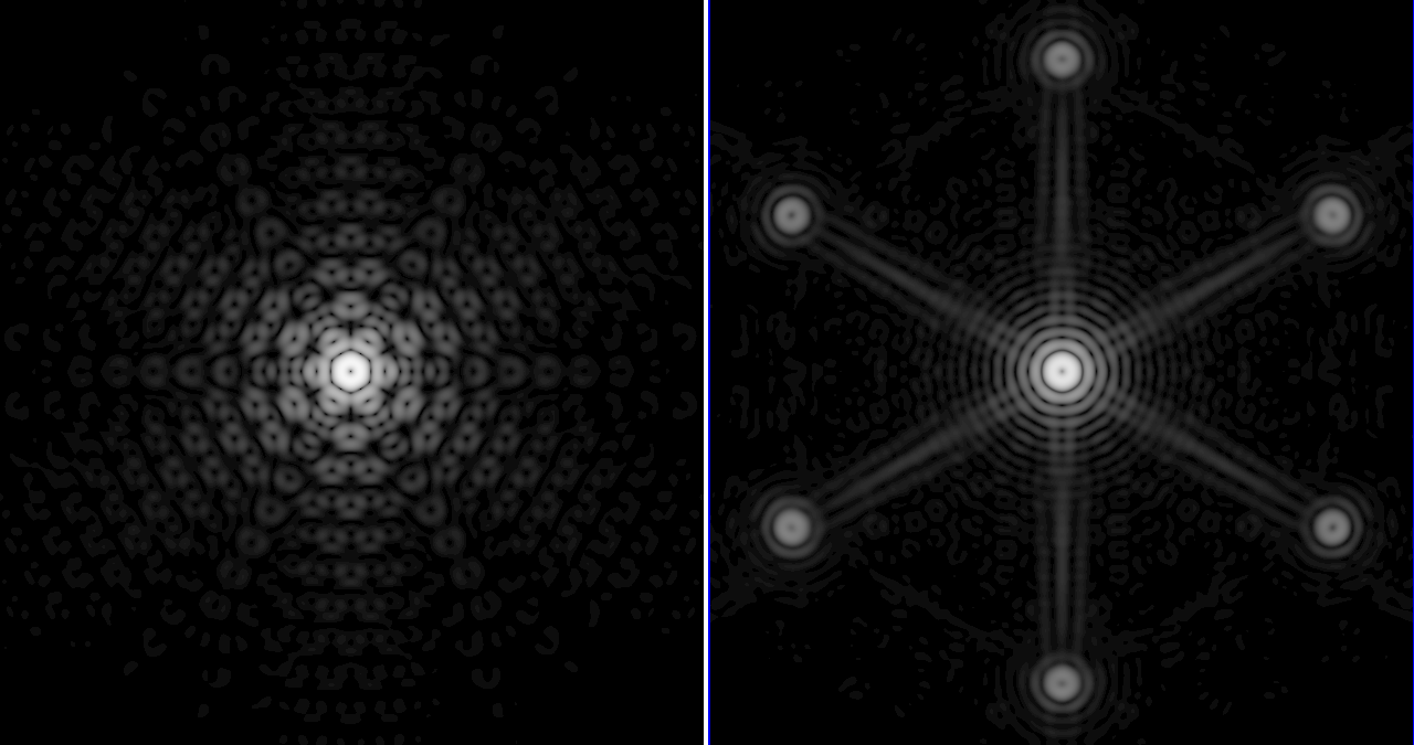
Figure 6 shows intensity images of a scene consisting of 5 equally bright point sources. The left images are obtained without a coronagraph, and simply show the imaging quality of the Subaru pupil in the absence of wavefront aberrations. The center column shows images in plane B of figure 2, immediately after the focal plane mask. The focal plane mask in the low IWA design (top) is more transmissive, and is also physically smaller. The large IWA design (bottom) introduces large off-axis aberrations due to the stong remapping. In the final coronagraphic images (right column), the central source is perfectly removed, and the images of the off-axis sources are sharp thanks to the inverse-PIAA optics.
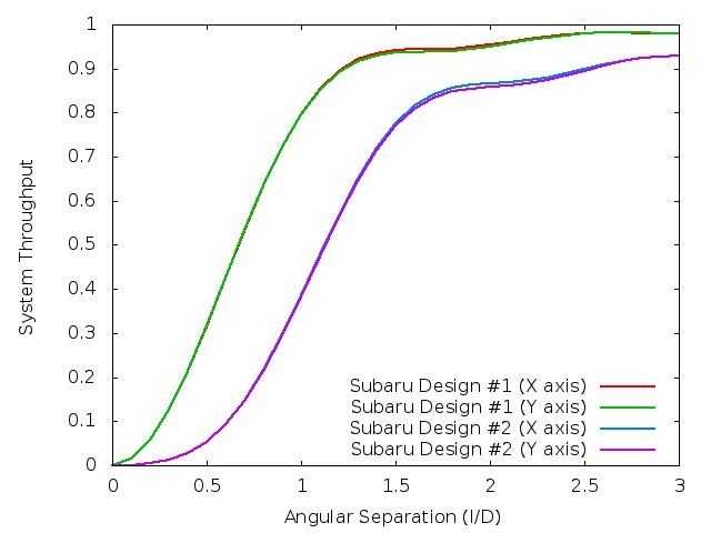
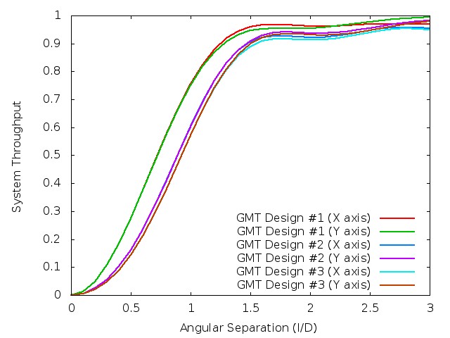
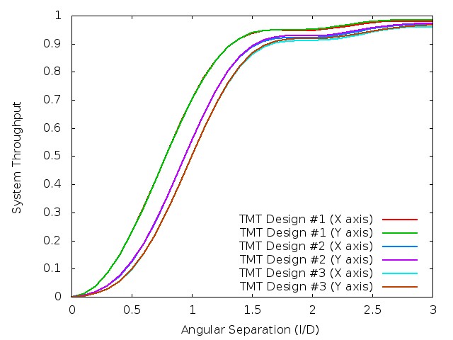
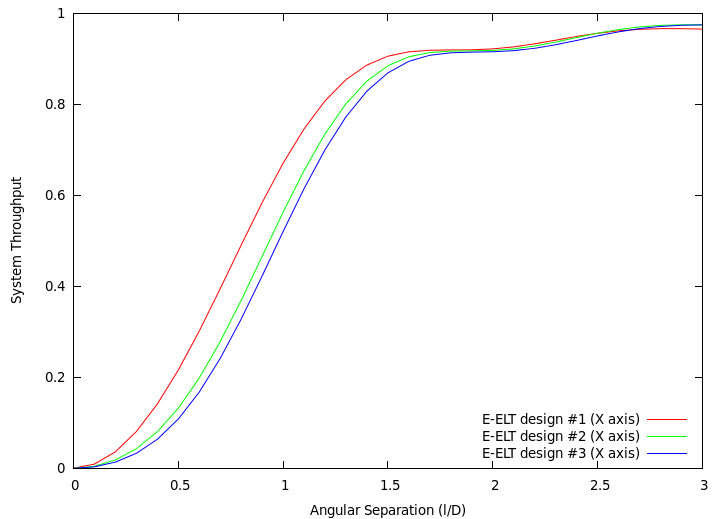
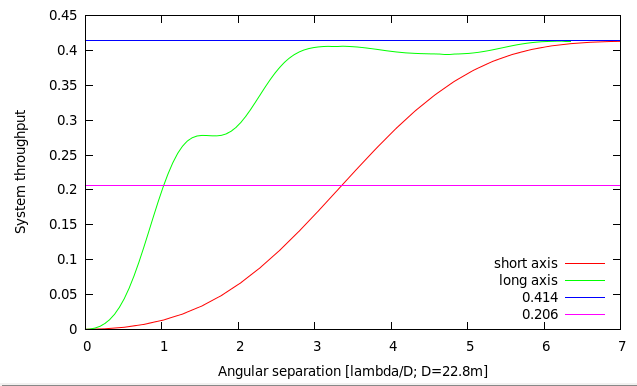
A quantitative measure of the coronagraphs' performance is provided in figure 3.4, which shows for each of the two designs the system off-axis throughput as a function of angular separation. For each design, the throughput is shown along the horizontal (x) and vertical (y) axes of figures 3.1, 3.2 and 3.3. For both designs, the throughput rises rapidly from zero (on-axis) to more than 80% at 1.5 λ/D. The small IWA design (design #1) has a 0.67 λ/D IWA, while the large IWA design's IWA is 1.11 λ/D. 3.3.2. Segmented pupils: Giant Magellan Telescope (GMT)The Giant Magellan Telescope (GMT) consists of one central 8.4-m circular segment, surrounded by a ring of six 8.4-m diameter segments. While the outer segments are unobscured, the central segment includes a central obstruction due to the secondary mirrors and its support structure.
3.3.3. Highly segmented pupils: Thirty Meter Telescope (TMT) and European Extremely Large Telescope (EELT)
3.4. DiscussionTable 2 summarizes the PIAACMC designs discussed in this section. For each design, the circular remapping function was first chosen, and is represented in the table by the parameter b, which is the diameter of the focal plane mask used to iteratively compute the generalized prolate function for a circular aperture. A small value of b indicates a weak apodization. The PIAA strength listed in the table is the surface brightness ratio between the brightest and faintest parts of the remapped beam, and is a function of only b. This ratio is a good indicator for both the level of distortions of the off-axis PSFs in the intermediate focal plane, and for the difficulty in making the PIAA optics. Current PIAA optics for conventional PIAA coronagraphs have a strength around 100, and any value below 100 therefore corresponds to PIAA optics that can be manufactured to nm-level surface accuracy without technological advances. For PIAA strength values above 100, a hybrid scheme where some of the edge apodization is offloaded to a conventional apodizer should be adopted, at the cost of lower throughput (typically up to 10% throughput loss) and loss of angular resolution (by typically up to 5%).
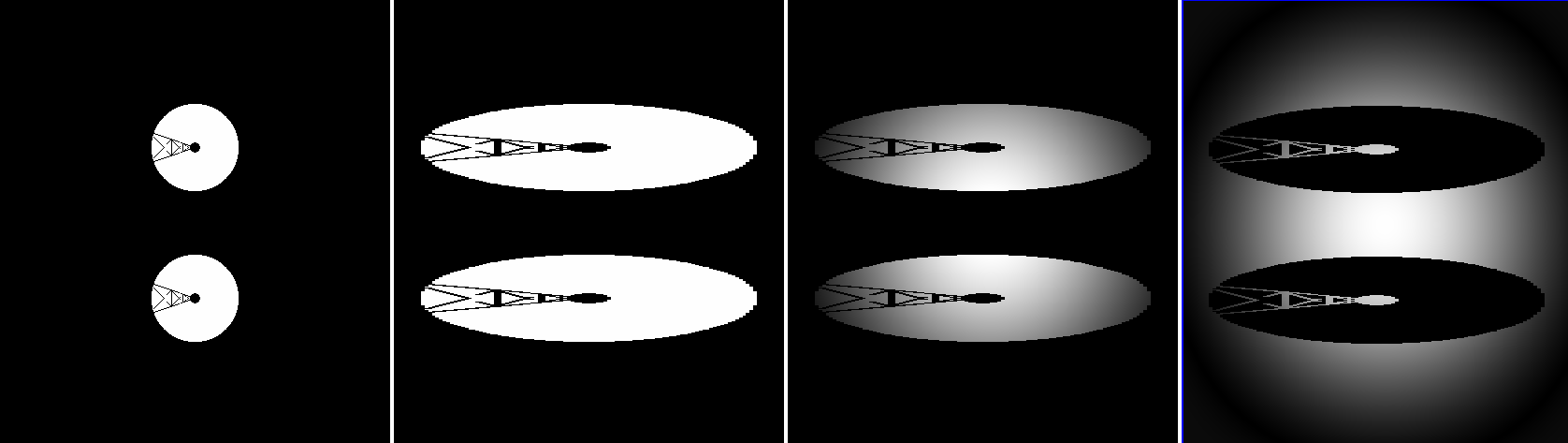
4. Particularly unfriendly apertures4.1. Description of the problemThe APCMLC and PIAACMC coronagraphs described in the previous section achieve full starlight suppression by performing, for each point in the output pupil, perfect destructive interference between the light that passes through the circular focal plane mask and the light that passes around it. These concepts therefore require that the telescope's non coronagraphic point spread function consist of a central diffraction spot within which a disk containing containing approximately half of the total PSF flux can be drawn, surrounded by other fainter diffractive features (rings, spikes). The examples given in the previous sections (Subaru, GMT, TMT, E-ELT) fulfill this requirement, as these pupil shapes are sufficiently close to a disk. While very sparse or elongated apertures are not compatible with the APCMLC and PIAACMC concepts as described so far, simple geometric transformations can extend the concepts to a wider range of pupil shapes. The Large Binocular Telescope (LBT) pupil is used in this section as an example of a sparse aperture with a strong aspect ratio: with its two centrally obscured 8.4-m diameter circular subapertures separated by 14.4m (center to center), the LBT pupil has a strong aspect ratio (8.4-m x 22.8-m). The corresponding non-coronagraphic PSF consists of three bright interference fringes within an envelope defined by the single aperture PSF. No circular mask can be drawn within the central bright fringe that contains half of the total PSF flux.
4.2. Using non-circular focal plane masksAs illustrated in figure x, stretching the LBT pupil along its narrow direction by a factor 4 creates a pupil sufficiently close to circular for the APCMLC and PIAACMC concepts as presented above. This stretch is equivalent to using an elliptical focal plane mask, which is 4 times longer in the direction running along the fringe in the PSF. Non-elliptical focal plane masks may also be adopted to further improve system throughput.
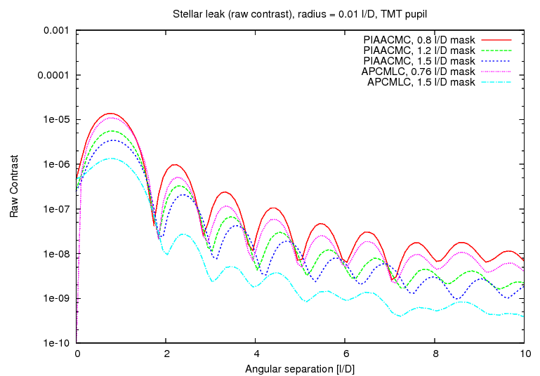
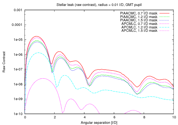
LBT APCMLC CORONAGRAPH DESIGN CHARACTERISTICS

FOCAL PLANE MASK SIZE: 3.099 x 0.775 l/D (elliptical)
FOCAL PLANE MASK TRANSMISSION: 99.04 %
FOCAL PLANE MASK PHASE: 1/2 lambda

PUPIL APODIZATION THROUGHPUT: 41.42 %

IWA (50% of max throughput), short axis: 3.35 lambda/D  (D=22.8 m)
IWA (50% of max throughput), short axis: 1.02 lambda/D  (D=22.8 m)
This approach may also be adopted to improve the APCMLC and PIAACMC performance for non-circular pupils: the focal plane mask shape should ideally be chosen to best match the non-coronagraphic PSF in order to maximize the conventional apodizer's transmission. For example, the generalized prolate function for the Subaru Telescope PIAACMC design #1 is slightly elongated due to the off-axis spider vanes. This produces a slight mismatch with the circular symmetric remapping function, which is absorbed by the conventional apodizer. Most of the conventional apodizer's light loss (0.1% total) is due to this mismatch. For this example, using an slightly elliptical focal plane mask would only improve throughput by at most 0.1% since the pupil is very close to being circular. More importantly, the elliptical focal plane mask may allow high performance operation of the PIAACMC without an apodizer. 4.3. Pupil remappingWith extremely sparse pupil geometries, the re-design of the focal plane mask geometry may not be sufficient to adapt the pupil shape to the APCMLC and PIAACMC requirements. In this case, geometrical transformation of the sparse entrance pupil into a more compact geometry can be achieved through pupil remapping. This scheme was explored to implement coronagraphy on sparse aperture [Riaud et al. 2002] [Guyon & Roddier 2002], and commonly referred to as the hypertelescope concept. Even if pupil remapping is not required, it may be useful to improve the APCMLC and PIAACMC system throughput. With sparse apertures, the apodizer becomes less transmissive: for example, the LBT pupil APCMLC design given in this section offers a 41% throughput, which is significantly less than the ~60% throughput of comparable APCMLC designs for the Subaru, GMT, TMT and E-ELT pupils. Bringing the LBT subapertures closer together with periscope-like optics would allow for higher throughput in the coronagraph. In order to maintain a good image quality over a wide field of view, the original pupil geometry should be re-created prior to the final imaging focal plane: the compact pupil is only an intermediate step required for efficient removal of the central source's light. 5. Sensitivity to stellar angular size5.1. AmplitudeCoronagraphs with small inner working angle (IWA) are sensitive to stellar angular size, and the small-IWA APCMLC and PIAACMC designs described in this paper are no exception. The coronagraph leaks due to stellar angular size are proportional to the square of the stellar radius, as the coronagraph designs yield 2-nd order nulls (a universal property of all small-IWA coronagraphs). Radial profiles for these leaks have been computed by incoherent summing of several hundred coronagraphic PSFs computed for a regular grid sampling of the stellar disk, and are shown in the figures below, and can reach 1e-5 contrast in at the IWA for a 0.01 l/D radius stellar disk.
5.2. Impact on high contrast detections: ground-based ELTsCoronagraphic leaks due to stellar angular diameter can be numerically subtracted from the science image, but will contribute photon noise. For ground-based detection of high contrast planets, the most challenging science goal is the direct imaging of reflected light exoplanets in the habitable zone of nearby M-type stars. The planet-to-star angular separation is then between 10mas and 20mas, and the contrast for a 2x Earth diameter planet is approximately 1e-7. The stellar diameter is typically around 0.01 l/D (a late M-type star with a 0.2 Sun radius size at 10 pc is 0.1 mas radius) and the stellar leak is then at the ~1e-5 raw contrast level. This level of stellar leak is approximately equal to the raw contrast contribution of residual atmospheric speckles after an Extreme-AO system, so stellar leak is not expected to be the dominant contributor in the detection error budget, and the most aggressive small IWA coronagraph designs may be employed on ground-based ELTs. 5.3. Impact on high contrast detections: Space-based coronagraphy
6. ConclusionsThe APCMLC and PIAACMC concepts, previously proposed for unobstructed circular apertures, are also applicable to telescopes with arbitrary pupil shapes. Their performance is largely unaffected by aperture shape, and full throughput low-IWA coronagraphy is therefore theoretically possible on any pupil shape with the PIAACMC. The demonstration that the coronagraph with the highest known theoretical performance can be applied on any pupil may remove the requirement that a future space-based exoplanet direct imaging mission should use an off-axis telescope. On ground-based telescopes, which adopt optical designs which are generally not driven by coronagraphy, high efficiency coronagraphy at and within 1 λ/D is possible, potentially allowing direct imaging of habitable planets around nearby M-type main sequence stars for which the planet to star contrast is favorable but the angular separation is extremely challenging and requires ~λ/D IWA even on a 30-m class telescope. Manufacturing and implementation challenges have not been addressed in this paper. Manufacturing an achromatic focal plane mask for the APCMLC or PIAACMC is challenging, as its size should scale linearly with wavelength, and its complex amplitude transmission should be achromatic. Similar challenges have been previously addressed for other coronagraphs [Soummer et al 2011], using carefully designed multilayer coatings of variable thickness and/or sub-λ/D sized features optimized to produced the required chromatic dependence within the geometric pupil [Soummer et al 2003] [N'Diaye et al 2011]. The PIAA optics required for the PIAACMC are however not as challenging to manufacture as PIAA optics previously made for hard edged opaque focal plane masks, as the PIAACMC's entrance apodization is milder. As any high performance low IWA coronagraph, the PIAACMC performance is highly sensitive to residual wavefront errors, which must be actively sensed and controlled. The PIAACMC's high throughput is an asset for achieving the required wavefront quality, as wavefront sensing can be performed rapidly, using all incoming light. Page content last updated: 27/06/2023 06:35:52 HST html file generated 27/06/2023 06:34:38 HST |