- pos.1 offset RA=0, offset DEC=0
- pos.2 offset RA=-DITH, offset DEC=+DITH
- pos.3 offset RA=2*DITH, offset DEC=0
- pos.4 offset RA=0, offset DEC=-2*DITH
- pos.5 offset RA=-2*DITH, offset DEC=0
- For example, the position with PA=90 (North up) will be center -> bottom left -> bottom right -> top right -> top left
(ii) GRISM and Echelle Spectroscopy
(a) ABBA mode: 2-points nodding pattern along the slit
A B
* * A->B->B->A
| | <----- nodding width (=DITH)
Observers can set the nodding width (=DITH) which is the distance between two small verticals sticks. The points A and B are DITH / 2 away from the target coordinate along the slit.
(b) OSO mode: Object-Sky-Object for extended objects
Observer can set the Offset (RA_OFFSET,
DEC_OFFSET) between Object and Sky. Object can be returned at
a different position on the slit if you set the DITH
parameter which is the small deviation between the positions of
Objects before and after the Sky.
*OSSO mode (Object-Sky-Sky-Object) is also possible
(c) Slit Scanning Mode
Scanning direction is perpendicular to the
slit. The setting paremeters for scanning are (Relative_OFFSET, EXPTIME,
COADDS) for each slit position.
* Warning: GRISM mode does not have slit
viewer. The accuracy of slit position depends on the telescope tracking
by AO system, or should be manually adjusted in case that AO cannot be used.
(iii) POLARIMETRY
[2] Description of Object list
The objects should be defined in the section of
# AliasNAME=OBJECT="objectname" RA=hhmmss.sss DEC=sddmmss.ss EQUINOX=yyyy.y FIELD_PA=field_pa
#Spectroscopy
# AliasNAME=OBJECT="objectname" RA=hhmmss.sss DEC=sddmmss.ss EQUINOX=yyyy.y SLIT_PA=slit_pa
#Select Guide Star Mode (GSMODE) of AO observation for AO188+IRCS observation
#Natural Guide Star : GSMODE="NGS", Laser Guide Star : GSMODE="LGS"
# for examples
# Vega RA= 18:36:56.34 DEC=+38:47:01.29 (2000.0) PA=0 degree
# with AO188/NGS
# VEGAIM=OBJECT="Vega" RA=183656.34 DEC=+384701.29 EQUINOX=2000.0 FIELD_PA=0.0 GSMODE="NGS"
# VEGASP=OBJECT="Vega" RA=183656.34 DEC=+384701.29 EQUINOX=2000.0 SLIT_PA=0.0 GSMODE="NGS"
# with AO188/LGS
# VEGAIM=OBJECT="Vega" RA=183656.34 DEC=+384701.29 EQUINOX=2000.0 FIELD_PA=0.0 GSMODE="LGS"
# VEGASP=OBJECT="Vega" RA=183656.34 DEC=+384701.29 EQUINOX=2000.0 SLIT_PA=0.0 GSMODE="LGS"
<Parameter_List>
# for IMAGING
OBJ1_NGSAO=OBJECT="Lynx A1" RA=053514.200 DEC=-052218.00 EQUINOX=2000.0 FIELD_PA=0.0 GSMODE="NGS"
OBJ1_LGSAO=OBJECT="Lynx A1" RA=053514.200 DEC=-052218.00 EQUINOX=2000.0 FIELD_PA=0.0 GSMODE="LGS"
TT1_LGSAO=OBJECT="LGS TT guide star" RA=053514.200 DEC=-052258.00 EQUINOX=2000.0 FIELD_PA=0.0 GSMODE="LGS"
# for SPECTROSCOPY (GRISM, ECHELLE)
OBJ1S_NGSAO=OBJECT="Lynx A1" RA=053514.200 DEC=-052218.00 EQUINOX=2000.0 SLIT_PA=90.0 GSMODE="NGS"
OBJ1S_LGSAO=OBJECT="Lynx A1" RA=053514.200 DEC=-052218.00 EQUINOX=2000.0 SLIT_PA=90.0 GSMODE="LGS"
TT1S_LGSAO=OBJECT="LGS TT guide star" RA=053514.200 DEC=-052258.00 EQUINOX=2000.0 SLIT_PA=90.0 GSMODE="LGS"
!!! For non-sidereal targets, !!!
# Object for IMAGING
MOON_IM=OBJECT="Moon" RA=053514.200 DEC=-052218.00 EQUINOX=2000.0 FIELD_PA=0.0 COORD=FILE TARGET="08 Moon.dat" (**)
# Object for SPECTROSCOPY
MOON_SP=OBJECT="Moon" RA=053514.200 DEC=-052218.00 EQUINOX=2000.0 SLIT_PA=0.0 COORD=FILE TARGET="08 Moon.dat"(**)
</Parameter_List >
Notice:
OBJ1(*1)=OBJECT="Lynx_A1"
RA=053514.200 DEC=-052218.00(*2) EQUINOX=2000.0
FIELD_PA(*3)=0.0
(*1) Just an alias name, which
should be capital.
(*2) RA=hhmmss.sss DEC=±ddmmss.ss
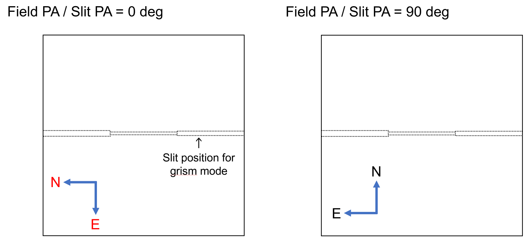
(*3) -. "FIELD_PA" means the position angle (degree) of the IRCS CAM array (Imaging).
The up direction of CAM image
is north when FIELD_PA=90 with
AO188.
-. "SLIT_PA" means the position angle (degree) of the IRCS
slits for spectroscopic modes.
If SLIT_PA=0, the direction
of slit length parallels North-South direction.
-.
The position angle (PA) is defined as the angular offset in
degrees relative to the
north celestial pole. The PA is measured from North to East,
counterclockwise direction.
-.Defalut SLIT_PA is 0 degree. If the SLIT_PA is not 0 degree,
the SLI_PA=<PA> should be
included in the "GETOBJECT" command line.
!!! For non-sidereal
targets, !!!
If you have a non-sidereal object, you
should make the non-sidereal tracking
file(**).
Please see:
https://www.naoj.org/Telescope/Tracking/NonSidereal/
.
(**) "Moon.dat" is the file for non-sidereal tracking which you made.
[3] Observation Procedure Script
Generally, the one complete set of the observational script consists of three parts as follows:(1) SETUPFIELD <$DEF_Mode> <$DEF_Mechanism> <$Object_name>
(2) CHECKFIELD <$DEF_Mode> <$DEF_Mechanism> <EXPTIME=sec>
(3) GETOBJECT <$DEF_OBSMode> <EXPTIME=sec> <DITH=arcsec> <COADDS=n> <NDUMMYREAD=n> <FIELD_PA or SLIT_PA=deg> <parameters depending on observational mode>
# For AO observation, TMODE (Tracking mode) should be indicated.
# TMODE=SID (for sidereal object), NON-SID (for non-sidereal object), ADI (for Angular Differential Imaging)
(i) IMAGING
## for no-AutoGuider without AO ##
SetupField $DEF_IMSTA $DEF_IMK $OBJ1_NGSAO
CheckField $DEF_IMSTA $DEF_IMK EXPTIME=10
GetObject $DEF_IMS5N EXPTIME=60 DITH=10.0 COADDS=1 NDUMMYREAD=0
## for with AO ##
# for Sidereal target : target object == TT guide star #
SetupField $DEF_IMSTA $DEF_IMK $OBJ1_NGSAO TMODE=SID
SetupField $DEF_IMSTA $DEF_IMK $OBJ1_LGSAO TMODE=SID
# for LGS when TT guide star != target object #
SetupField $DEF_IMSTA $DEF_IMK $TT1_LGSAO TMODE=SID
AO188_OFFSET_RADEC $DEF_AOLN $OBJ1_LGSAO
# for ADI mode #
SetupField $DEF_IMSTA $DEF_IMK $OBJ1_NGSAO TMODE=ADI
SetupField $DEF_IMSTA $DEF_IMK $OBJ1_LGSAO TMODE=ADI
#for all AO modes #
CheckField $DEF_IMSTA $DEF_IMK EXPTIME=10
GetObject $DEF_IMS9A EXPTIME=60 DITH=3.0 COADDS=1 PIXSCALE=52MAS NDUMMYREAD=0 MODE=AOP
# without AO #
!!! For non-sidereal targets, !!!
SetupField $DEF_IMSTA $DEF_IMK $MOON TMODE="NON-SID"
CheckField $DEF_IMSTA $DEF_IMK EXPTIME=10
GetObject $DEF_IMS9N COORD=FILE EXPTIME=60 DITH=3.0 COADDS=1 NDUMMYREAD=0
# with AO #
SetupField $DEF_IMSTA $DEF_IMK $MOON TMODE="NON-SID"
CheckField $DEF_IMSTA $DEF_IMK EXPTIME=10
GetObject $DEF_IMS9A COORD=FILE EXPTIME=60 DITH=3.0 COADDS=1 PIXSCALE=52MAS NDUMMYREAD=0 MODE=AOP
-
SetupField is for;
(a) moving telescope to the star; OBJ1 ( "OBJ1" defined in object list [1] ),
(b) moving rotator to "FIELD_PA" value defined in object list [1],
(c) moving IRCS mechanism to K-band imaging setting ("DEF_IMK" means K-band imaging setting),
(d) starting auto-guiding.
The first parameter, $DEF_IMSTA, determines your observing mode options as follows:
$DEF_IMSTN : no-guiding (without auto-guiding)
$DEF_IMSTA : with AO188
The
second parameter, $DEF_IMK, determines the mechanical
setting (Filters and Pixel scale: 52mas, 20 mas)
(*) You can find the mechanism definition which you want in
the "[A2] Mechanism Definition" section of this document.
The
third parameter is your object name defined in the object
list section [1].
-
CheckField is for;
(a) taking a picture and check the field obseved with exposure time of ## sec ( e.g. for 10 sec EXPTIME=10).
The first and second parameters are the same with those in
the "SetupField".
The 3rd parameter defines the integration (exposure) time
for test shot.
-
GetObject is for;
(a) starting dithering procedure with exposure time of 60 sec (EXPTIME=60) and dithering width of 10.0 arcsec (DITH=10.0).
"EXPTIME" and "DITH" for the integration time in sec and dithering
width in arcsecond.
The first parameter, e.g.
$DEF_IMS5A, determines the
dithering pattern and options as
follows:
[one frame]
$DEF_IMSTN : no-guiding (without auto-guiding)
$DEF_IMSTA : with AO188
[5 points dithering]
$DEF_IMS5N : no-guiding (without auto-guiding)
$DEF_IMS5A : with AO188
[9 points dithering]
$DEF_IMS9N : no-guiding (without auto-guiding)
$DEF_IMS9A : with AO188
(b) AO parameters: PIXSCALE= 52mas or 20 mas, MODE=TTNULL or AOP, TTSLEEP=3 (sec), TTSTEP= int(DITH/3)+1
(c) COORD=FILE should be set for non-sidereal target.
(i') L'-band Imaging
-< begin >---------------------------------------------------------------------------
SetClock $DEF_IRST SLWCNT=1
SetupField ....
CheckField ....
GetObject .... NDUMMYREAD=0 ....
SetClock $DEF_IRST SLWCNT=16
-< end >-----------------------------------------------------------------------------
L'-band imaging is a special mode because the thermal
background is too high.
You
should add two command lines to the nominal imaging
procedure, which
change IRCS clock pattern to decrease the shortest
integration time from 0.41 s to 0.12 s.
In
addition, "NDUMMYREAD=0" must be inserted into "GetObject"
line.
(ii) Grism Spectroscopy
## for not using AutoGuider without AO ##
SetupField $DEF_GRSTA $DEF_IMK $OBJ1S_NGS
CheckField $DEF_GRSTA $DEF_GRK EXPTIME=10
GetObject $DEF_GRD2N EXPTIME=120 DITH=7.0 COADDS=1 SLIT_PA=90.0 (;ABBA mode along the slit)
GetObject $DEF_GRD2XS1N EXPTIME=120 DITH=0.0 SLIT_PA=90.0 RA_OFFSET=30 DEC_OFFSET=1800 (;Obj-Sky-Obj' mode)
GetObject $DEF_GRSSN SCAN_PAT=[-0.3 120 1 0.15 120 1 0.15 120 1 0.15 120 1 0.15 120 1 -0.3 0 1] EXPTIME_SV=0.5 SLIT_PA=90.0 (;SlitScan mode)
## for with AO ##
# for target object == TT guide star #
SetupField $DEF_GRSTA $DEF_IMK $OBJ1S_NGSAO TMODE=SID
SetupField $DEF_GRSTA $DEF_IMK $OBJ1S_LGSAO TMODE=SID
# for LGS : target object != TT guide star #
SetupField $DEF_GRSTA $DEF_IMK $TT1S_LGSAO TMODE=SID
AO188_OFFSET_RADEC $DEF_AOLN $OBJ1S_LGSAO
CheckField $DEF_GRSTA $DEF_GRK EXPTIME=10
GetObject $DEF_GRD2A EXPTIME=120 DITH=7.0 COADDS=1 PIXSCALE=52MAS MODE=AOP (; ABBA mode along the slit)
GetObject $DEF_GRD2XS1A EXPTIME=120 DITH=3.0 RA_OFFSET=30 DEC_OFFSET=1800 MODE=AOP (; Obj-Sky-Obj' mode)
GetObject $DEF_GRSSA SCAN_PAT=[-0.3 120 1 0.15 120 1 0.15 120 1 0.15 120 1 0.15 120 1 -0.3 0 1] EXPTIME_SV=0.5 (; SlitScan mode)
!!! For non-sidereal targets, !!!# for without AO #
Please select "no-guiding" and add "COORD=FILE" as follows.
SetupField $DEF_GRSTN $DEF_IMK $MOON
CheckField $DEF_GRSTN $DEF_GRK EXPTIME=10
GetObject $DEF_GRD2N EXPTIME=120 DITH=7.0 SLIT_PA=90.0 COORD=FILE
#for without AO
SetupField $DEF_GRSTA $DEF_IMK $MOON TMODE="NON-SID"
CheckFIELD $DEF_GRSTA $DEF_GRK EXPTIME=10
GetObject $DEF_GRD2N EXPTIME=120 DITH=7.0 COORD=FILE
# for with AO
SetupField $DEF_GRSTA $DEF_IMK $MOON TMODE="NON-SID"
CheckField $DEF_GRSTA $DEF_GRK EXPTIME=10
GetObject $DEF_GRD2A EXPTIME=120 DITH=7.0 COORD=FILE MODE=AOP
-
SetupField is for;
(a) moving telescope to the star; OBJ1S_* ( "OBJ1S_*" defined in object list [1] ),
(b) moving image rotator to "SLIT_PA" value defined in object list [1].
**WARNING** In "GetObject" command, the "SLIT_PA" SHOULD BE GIVEN with the same PA value in WITHOUT AO mode, while SHOULD NOT BE GIVEN for WITH AO,
(c) moving IRCS mechanism to K-band imaging setting ("DEF_IMK" means K-band imaging setting for Camera side),
(d) taking pictures to put the star on the position of the slit (Pick-up procedure),
(e) starting auto-guiding.
The first parameter, $DEF_GRSTA, determines your observing mode options as follows:
$DEF_GRSTN : no-guiding (without auto-guiding)
$DEF_GRSTA : with AO188
(!) We don't recommend you to use no-guiding for GRISM spectroscopy mode.
-
CheckField is for;
(a) changing the mechanism for K-band grism setting ("DEF_GRK" means K-band grism setting. Please refer "[A2] Mechanism Definition" section for your observation),
(b) taking a spectrum to check intensity level with exposure time of 10sec ("EXPTIME"=10).
-
GetObject for ABBA mode ;
(a) Start 2-points nodding procedure with exposure time of 120sec ("EXPTIME"=120) and nodding width of 7.0 arcsec ("DITH"=7.0).
(!) For without AO, please explicitly mention slit position angle which is the same as "SLIT_PA" in object list.
-
GetObject for OSSO(Object-Sky-Object) sequence;
(a) The sky position is located at (RA_OFFSET, DEC_OFFSET) from the object,
(b) The object position is the same before and after the sky on the slit (DITH = 0.0).
RA_OFFSET and DEC_OFFSET are the offsets from the object
to reach the sky position in RA and DEC (in arcsecond).
DITH is the WIDTH between the positions of object along
the slit before and after the sky position.
-
GetObject for Slit Scanning sequence;
(a) Scan between +/- 0.3 arcsec from the object with 0.15" interval perpendicular to the slit and return to the initial object position,
(b) For each slit position, EXPTIME = 120 sec, COADDS=1 sec,
(c) The three parameters for each slit position are (Relative_OFFSET, EXPTIME, COADDS) in SCAN_PAT.
(-0.3 120 1) (0.15 120 1) (0.15 120 1) (0.15 120 1) (0.15 120 1) (-0.3 0 1)
|<------(-0.3")--------(object)
|----0.15"-->|----0.15"-->|---0.15"--->|---0.15"--->|
|<-------(-0.3")----------|
Please set the exact scanning
pattern in SCAN_PAT.
(d)
EXPTIME_SV sets the exposure time of the Slit Viewer
(Camera side).
The first parameter, $DEF_GRD2V, determines the
nodding pattern and options as follow:
The last character of the 1st parameter means:
N: no-guiding, V: with auto-guiding, AN: with AO but without
auto-guiding, AV: with both AO and auto-guiding
[One frame]
$DEF_GRSTN : no-guiding (without auto-guiding)
$DEF_GRSTA : with AO188[A-B-B-A pattern: 2-points nodding along the slit]
$DEF_GRD2N
$DEF_GRD2A
[Object-Sky-Object for extended objects]
(Please set the RA_OFFSET and DEC_OFFSET in GetObject command.)
$DEF_GRD2XS1N
$DEF_GRD2XS1A
[Object-Sky-Sky-Object for extended stars]
(Please set the RA_OFFSET and DEC_OFFSET in GetObject command.)
$DEF_GRD2XS2N
$DEF_GRD2XS2A[Slit Scanning]
$DEF_GRSSA
(iii) Echelle Spectroscopy
## for not using AutoGuider without AO ## SetupField $DEF_ECSTA $DEF_ECJ_N $DEF_IMK $OBJ1S_NGS
CheckField $DEF_ECSTA $DEF_ECJ_N EXPTIME=10
GetObject $DEF_ECD2N EXPTIME=300 DITH=2.5 SLIT_PA=90.0 (;ABBA mode along the slit)
GetObject $DEF_ECD2XS2N EXPTIME=300 DITH=0.0 SLIT_PA=90.0 RA_OFFSET=30 DEC_OFFSET=1800 (;Obj-Sky-Object mode)
GetObject $DEF_ECSSN SCAN_PAT=[-0.3 120 1 0.15 120 1 0.15 120 1 0.15 120 1 0.15 120 1 -0.3 0 1] EXPTIME_SV=0.5 SLIT_PA=90.0 (; SlitScan mode)
## for with AO ##
# for target obejct == TT guide star #
SetupField $DEF_ECSTA $DEF_IMK $OBJ1S_NGSAO TMODE=SID
SetupField $DEF_ECSTA $DEF_IMK $OBJ1S_LGSAO TMODE=SID
# for target obejct != TT guide star #
SetupField $DEF_ECSTA $DEF_IMK $TT1S_LGSAO TMODE=SID
AO188_OFFSET_RADEC $DEF_AOLN $OBJ1S_LGSAO
# for ADI mode #
SetupField $DEF_ECSTA $DEF_IMK $OBJ1S_NGSAO TMODE=ADI
SetupField $DEF_ECSTA $DEF_IMK $OBJ1S_LGSAO TMODE=ADI
# for All AO mode #
CheckField $DEF_ECSTA $DEF_ECJ_N EXPTIME=10
GetObject $DEF_ECD2A EXPTIME=120 DITH=1.5 COADDS=1 PIXSCALE=52MAS MODE=AOP (;ABBA mode along the slit)
GetObject $DEF_ECD2XS1A EXPTIME=120 DITH=3.0 RA_OFFSET=30 DEC_OFFSET=1800 MODE=AOP (; Obj-Sky-Obj mode)
GetObject $DEF_ECSSA SCAN_PAT=[-0.3 120 1 0.15 120 1 0.15 120 1 0.15 120 1 0.15 120 1 -0.3 0 1] EXPTIME_SV=0.5 (; SlitScan mode)
!!! For non-sidereal targets, !!!# for without AO #
Please select "no-guiding" and add "COORD=FILE" as follows.
SetupField $DEF_ECSTN $DEF_IMK $MOON
CheckField $DEF_ECSTN $DEF_ECJ_N EXPTIME=10
GetObject $DEF_ECD2N EXPTIME=120 DITH=1.5 SLIT_PA=90.0 COORD=FILE
# for with AO
SetupField $DEF_ECSTA $DEF_IMK $MOON TMODE="NON-SID"
CheckField $DEF_ECSTA $DEF_ECJ_N EXPTIME=10
GetObject $DEF_ECD2A EXPTIME=120 DITH=1.5 COORD=FILE MODE=AOP
-
SetupField is for;
(a) moving telescope to the star; OBJ1S_* ( "OBJ1S_*" defined in object list [1]),
(b) moving rotator to "SLIT_PA" value defined in object list [1].
**WARNING ** In "GetObject" command, the "SLIT_PA" SHOULD BE GIVEN with the same PA value in WITHOUT AO mode, while SHOULD NOT BE GIVEN for WITH AO,
(c) moving IRCS mechanism to K-band imaging setting (for slit viewer) and J-band echelle setting,
("DEF_ECJ_N" means J-band echelle setting with the narrow (0".14) slit.)
<*> The suffix should be "_N", "_M" or "_W", which means Narrow(0".14), Mideum(0".27) and Wide(0".54) respectively.
(Please refer "[A2] Mechanism Definition" section for your observation.),
(d) taking pictures to put the star on the position of slits (Pick-up procedure),
(e) starting auto-guiding.
The first parameter, $DEF_ECSTA, determines your observing mode options as follows:
$DEF_ECSTN : no-guiding (without auto-guiding)
$DEF_ECSTA : with AO188
(!) We don't recommend you to use no-guiding for this mode.
-
CheckField is for;
(a) changing the mechanism for J-band echelle setting,
(b) taking a echelle spectrum and check the intensity level with exposure time of 10 sec ("EXPTIME"=10).
-
GetObject for ABBA mode;
(a) starting 2-points nodding procedure with exposure time of 300 sec ("EXPTIME"=300) and nodding width of 2.5 arcsec ("DITH"=2.5).
(!) For without AO, please explicitly mention slit position angle which is the same as "SLIT_PA" in object list.
-
GetObject for OSSO(Object-Sky-Sky-Object) sequence;
(a) The sky position is located at (RA_OFFSET, DEC_OFFSET) from the object,
(b) The object position is the same before and after the sky on the slit (DITH = 0.0).
RA_OFFSET and DEC_OFFSET are the offsets from the
object to reach the sky position in RA and DEC (in
arcsecond).
DITH is the WIDTH between the positions of object
before and after the sky along the slit.
-
GetObject for slit scanning sequence;
(a) Scan between +/- 0.3 arcsec from the object with 0.15" interval perpendicular to the slit and return to the object position,
(b) for each slit position, EXPTIME = 120 sec, COADDS=1 sec,
(c) the three parameters for each slit position are (Relative_Offset, EXPTIME, COADDS) in SCAN_PAT
(-0.3 120 1) (0.15 120 1) (0.15 120 1) (0.15 120 1) (0.15 120 1) (-0.3 0 1)
|<------(-0.3")--------(object)
|----0.15"-->|----0.15"-->|---0.15"--->|---0.15"--->|
|<-------(-0.3")----------|
Please set the exact scanning pattern in SCAN_PAT.
(d) EXPTIME_SV sets the exposure time of the Slit Viewer (Camera side).
The first parameter, $DEF_ECD2A, determines the nodding pattern and options as follow:
The last character of the 1st parameter means:
N: no-guiding, A: with AO.
[One frame]
$DEF_ECSTN : no-guiding (without auto-guiding)
$DEF_ECSTA : with AO188[A-B-B-A pattern: 2-points nodding along the slit]
$DEF_ECD2N
$DEF_ECD2A[Object-Sky-Object for extended objects]
(Please set the RA_OFFSET and DEC_OFFSET in GetObject command.)
$DEF_ECD2XS1N
$DEF_ECD2XS1A[Object-Sky-Sky-Object for extended stars]
(Please set the RA_OFFSET and DEC_OFFSET in GetObject command.)
$DEF_ECD2XS2N
$DEF_ECD2XS2A[Slit Scanning]
$DEF_ECSSA
[A1] Mechanism Definition (for $DEF_Mechanism in SetupField and CheckField commands)
| [i] IMAGING | 52 mas | 20 mas |
| Broad Band Setting |
|
|
| Z-band | DEF_IMZ | DEF_IM20Z |
| J-band | DEF_IMJ | DEF_IM20J |
| H-band | DEF_IMH | DEF_IM20H |
| K-band | DEF_IMK | DEF_IM20K |
| K'-band | DEF_IMKP | DEF_IM20KP |
| H+K'-band | DEF_IMHK | DEF_IM20HK |
| L'-band | DEF_IMLP | DEF_IM20LP |
| M'-band | -- | DEF_IMMP |
| Narrow Band Setting |
|
|
| CH4 SHORT | DEF_IMCH4S | DEF_IM20CH4S |
| H-continuum | DEF_IMHC | DEF_IM20HC |
| CH4 LONG | DEF_IMCH4L | DEF_IM20CH4L |
| [Fe II] | DEF_IMFE | DEF_IM20FE |
| NB2070 | DEF_IMNB2070 | DEF_IM20NB2070 |
| NB2090 | DEF_IMNB2090 | DEF_IM20NB2090 |
| H2 1-0 | DEF_IMH210 | DEF_IM20H210 |
| Br_gamma | DEF_IMBRG | DEF_IM20BRG |
| K-continuum | DEF_IMKC | DEF_IM20KC |
| H2O Ice | DEF_IMH2O | DEF_IM20H2O |
| PAH | DEF_IMPAH | DEF_IM20PAH |
| H3+ | DEF_IMH3P | DEF_IM20H3P |
| Br_Alpha | DEF_IMBRA |
DEF_IM20BRA |
| With Coronagraphic masks (0.8", 0.6", 0.15") | Attach "_MSK" at the end (e.g. DEF_IMZ_MSK, ...) | Attach "_MSK" at the end (e.g. DEF_IM20Z_MSK, ...) |
|
[ii] GRISM SPECTROSCOPY
There are two reflective slits and the
slit widths are as follows: |
52 mas (w/ Refl_3W slit, w/ Refl_4 slit ) | 20 mas (w/ Refl_4 slit ) |
| zJH GRISM | DEF_GZRJH, DEF_GRZJH_N | |
| HK GRISM | DEF_GRHK, DEF_GRHK_N | |
| Iz | DEF_GRIZ, DEF_GRIZ_N | DEF_GR20IZ |
| zJ | DEF_GRZJ, DEF_GRZJ_N | DEF_GR20ZJ |
| J | DEF_GRJ, DEF_GRJ_N | DEF_GR20J |
| H | DEF_GRH, DEF_GRH_N | DEF_GR20H |
| K | DEF_GRK, DEF_GRK_N | DEF_GR20K |
| L | DEF_GRL, DEF_GRL_N | DEF_GR20L |
| PRISM | DEF_PRW, DEF_PRW_N | DEF_PRKL_N, DEF_PRKL (w/ Refl_3W slit) |
| [iii] ECHELLE SPECTROSCOPY | O.54" Slit | 0.27" Slit | 0.14" Slit |
| Iz | DEF_ECIZ_W | DEF_ECIZ_M | DEF_ECIZ_N |
| zJ | DEF_EC_ZJ_W | DEF_ECZJ_M | DEF_ECZJ_N |
| J | DEF_ECJ_W | DEF_ECJ_M | DEF_ECJ_N |
| H- | DEF_ECHM_W | DEF_ECHM_M | DEF_ECHM_N |
| H+ | DEF_ECHP_W | DEF_ECHP_M | DEF_ECHP_N |
| K- | DEF_ECKM_W | DEF_ECKM_M | DEF_ECKM_N |
| K+ | DEF_ECKP_W | DEF_ECKP_M | DEF_ECKP_N |
| K* | DEF_ECKH2_W | DEF_ECKH2_M | DEF_ECKH2_N |
| LA- | DEF_ECLAM_W | DEF_ECLAM_M | DEF_ECLAM_N |
| LA0 | DEF_ECLAZ_W | DEF_ECLAZ_M | DEF_ECLAZ_N |
| LA+ | DEF_ECLAP_W | DEF_ECLAP_M | DEF_ECLAP_N |
| LB- | DEF_ECLBM_W | DEF_ECLBM_M | DEF_ECLBM_N |
| LB0 | DEF_ECLBZ_W | DEF_ECLBZ_M | DEF_ECLBZ_N |
| LB+ | DEF_ECLBP_W | DEF_ECLBP_M | DEF_ECLBP_N |
| M-- | DEF_ECMMM_W | DEF_ECMMM_M | DEF_ECMMM_N |
| M- | DEF_ECMM_W | DEF_ECMM_M | DEF_ECMM_N |
| M+ | DEF_ECMP_W | DEF_ECMP_M | DEF_ECMP_N |
| M++ | DEF_ECMPP_W | DEF_ECMPP_M | DEF_ECMPP_N |
| H for [Fe II] lines (ECH=3610, XDS=-300) | DEF_ECHFE_W | DEF_ECHFE_M | DEF_ECHFE_N |
| K for H2 lines (ECH=6450, XDS=500) | DEF_ECKH2_W | DEF_ECKH2_M | DEF_ECKH2_N |
| L for CH4 lines (ECH=1200, XDS=670) | DEF_ECLCH_W | DEF_ECLCH_M | DEF_ECLCH_N |
| L for H3+ lines (ECH=8350, XDS=2912) | DEF_ECLH3_W | DEF_ECLH3_M | DEF_ECLH3_N |
| L for C2H6 lines (ECH=3350, XDS=250) | DEF_ECLC2H6_W | DEF_ECLC2H6_M | DEF_ECLC2H6_N |
| L for CH4 lines (2) (ECH=7350, XDS=-200) | DEF_ECLCH4_W | DEF_ECLCH4_M | DEF_ECLCH4_N |
| L for H2OIce (ECH=8150, XDS=1200) | DEF_ECLH2O_W | DEF_ECLH2O_M | DEF_ECLH2O_N |
| M for CO (ECH=8200, XDS=-5500) | DEF_ECMCO_W | DEF_ECMCO_M | DEF_ECMCO_N |
!! Customized set-up is available. Please see the following URL for detail information.
https://www.naoj.org/staff/pyo/Esimulator/README
[A2] OPE file
(Template)
Last updated: Oct 19 2020