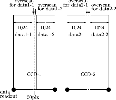
The HDS data unit includes the output of one CCD with 2048 (slit direction) by 4100 (dispersion direction) pixels (in the case without binning) and the over-scan region. Over-scan indicates the additional readout to the CCD pixels exposed. The data in the over-scan region provides the bias level for the frame itself.
Since there are two output points for each CCD, the unit of one output
is originally composed of 1024 × 4100 pixels. The over-scan
region (50 × 4100 pixels) is added to this data unit. One file
is composed of the two units, after the addition of the over-scan
region. Then the two files, corresponding to the two CCDs (as shown in
Figure ![[*]](crossref.png) ) are obtained by one exposure. Note that the above
explanation also applies to data obtained with binning of slit
direction in the readout, i.e., the over-scan region of the same size
(50 × 4100 pixels) is added to one data unit for the data with
binning. In the case of the 2 × 2 binning, the over-scan region
of 50 × 2050 pixels is added.
) are obtained by one exposure. Note that the above
explanation also applies to data obtained with binning of slit
direction in the readout, i.e., the over-scan region of the same size
(50 × 4100 pixels) is added to one data unit for the data with
binning. In the case of the 2 × 2 binning, the over-scan region
of 50 × 2050 pixels is added.
As mentioned in Section , it is desirable to correct the
variation of the bias level using the data in the over-scan region.
A sequential number (frame ID) is assigned to the data obtained with each exposure. Since two files are produced by one exposure, corresponding to the two CCDs, two frame IDs are given for each exposure. The frame IDs are the 8 figures following ``HDSA,'' beginning with 'HDSA00000001'. The number does not go backwards, and the number will be missing if the data acquisition is canceled after frame IDs have been assigned. The file name is produced by attaching the extension '.fits' to the frame ID (e.g., HDSA00000001.fits).
The FITS file obtained for each exposure consists of usual header/data unit,
an ASCII extension table, and its header. In the extension table, the
spectrum format (order, wavelength and position of the order projected on the
detector) is described based on the calculation using the setup parameters of
the gratings. Examples of a header unit and an ASCII extension table are given
in Section .
When the light monitor is used, a second ASCII extension table is attached to the above data format. In the extension table, the data obtained by the light monitor are recorded.