
Camera body disassembly: opening the outer camera case. Remove screws around the back of the camera body and prop open the camera. The back of the camera body (where the viewing screen is) comes out.
| |
Image 1 Camera body disassembly: opening the outer camera case. Remove screws around the back of the camera body and prop open the camera. The back of the camera body (where the viewing screen is) comes out. |
 |
Image 2 View of the back of the camera. There are several small connectors which need to be diconnected. Most of the connectors have a small hinge which is lifted to free the connector. |
 |
Image 3 View of the back of the camera after the connectors have been diconnected. The detector is behind the large metal plate in the center. Both the large metal plate and the electronic board around the detector assembly can now be removed to access the 3 detector positioning screws (location shown by the 3 arrows). |
 |
Image 4 Detailed view of one of the 3 detector positioning screws. The spring-loaded screws are used to adjust the detector position (focus and tip/tilt). A small metal plate is between the head of the screw and the detector unit. This plate is kept from rotating by a small black pin. The plate extends outward between two black plastic blocks, which provide a convenient reference to measure how deep the plate is compared to the camera body. |
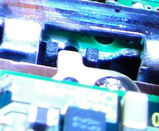 |
Image 4 (detail) This is a magnified view of the same detector positioning screw. Before removing the detector unit, the depth of each of the 3 positioning stages needs to be measured so that the detector unit can be re-positioned to the approximate same position during re-assembly. The two black blocks around the metal plate provide a good reference surface for this measurement. I used a digital caliper with 10 micron resolution for the measurement. |
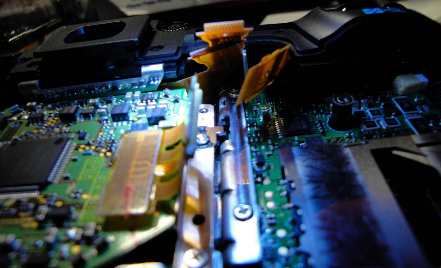 |
Image 5 This side view shows a different view of the detector positioning screw. |
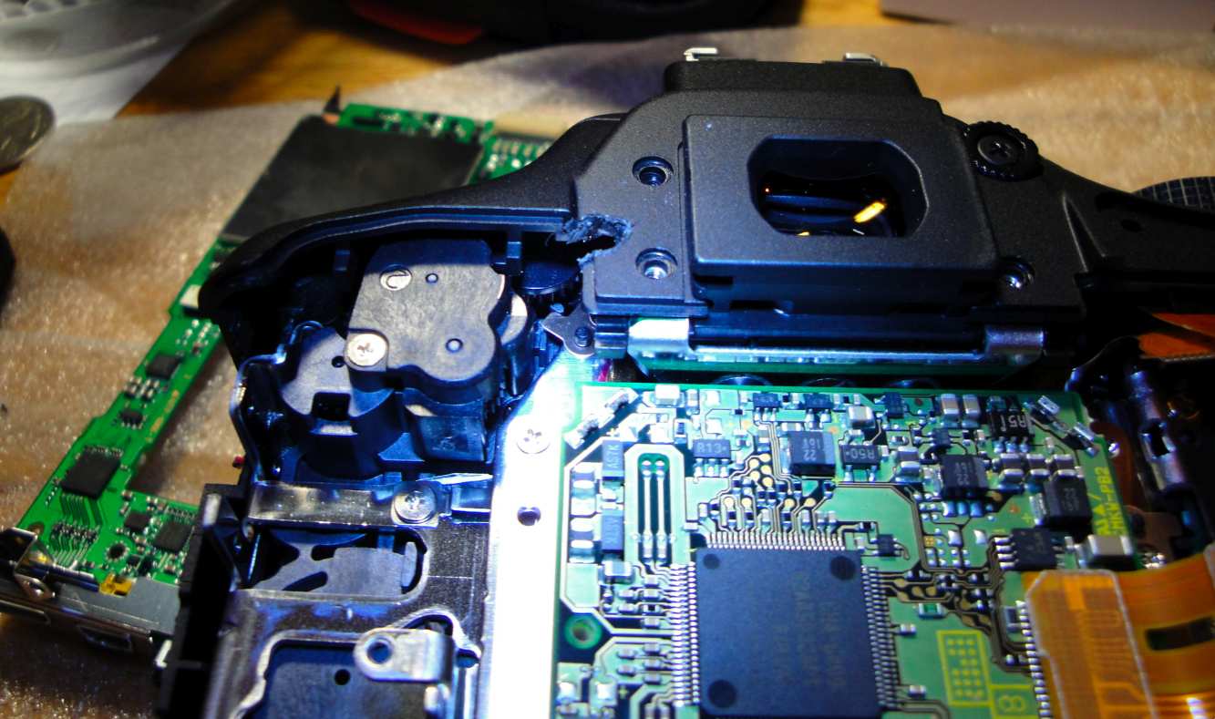 |
Image 6 Out of the 3 positioning screws, the top one is the hardest one to access. I had to drill a small hole in the camera case to access it. It is also probably possible to access it through a more complete disassembly of the camera. This view shows the hole I drilled and the positioning screw assembly just below it. |
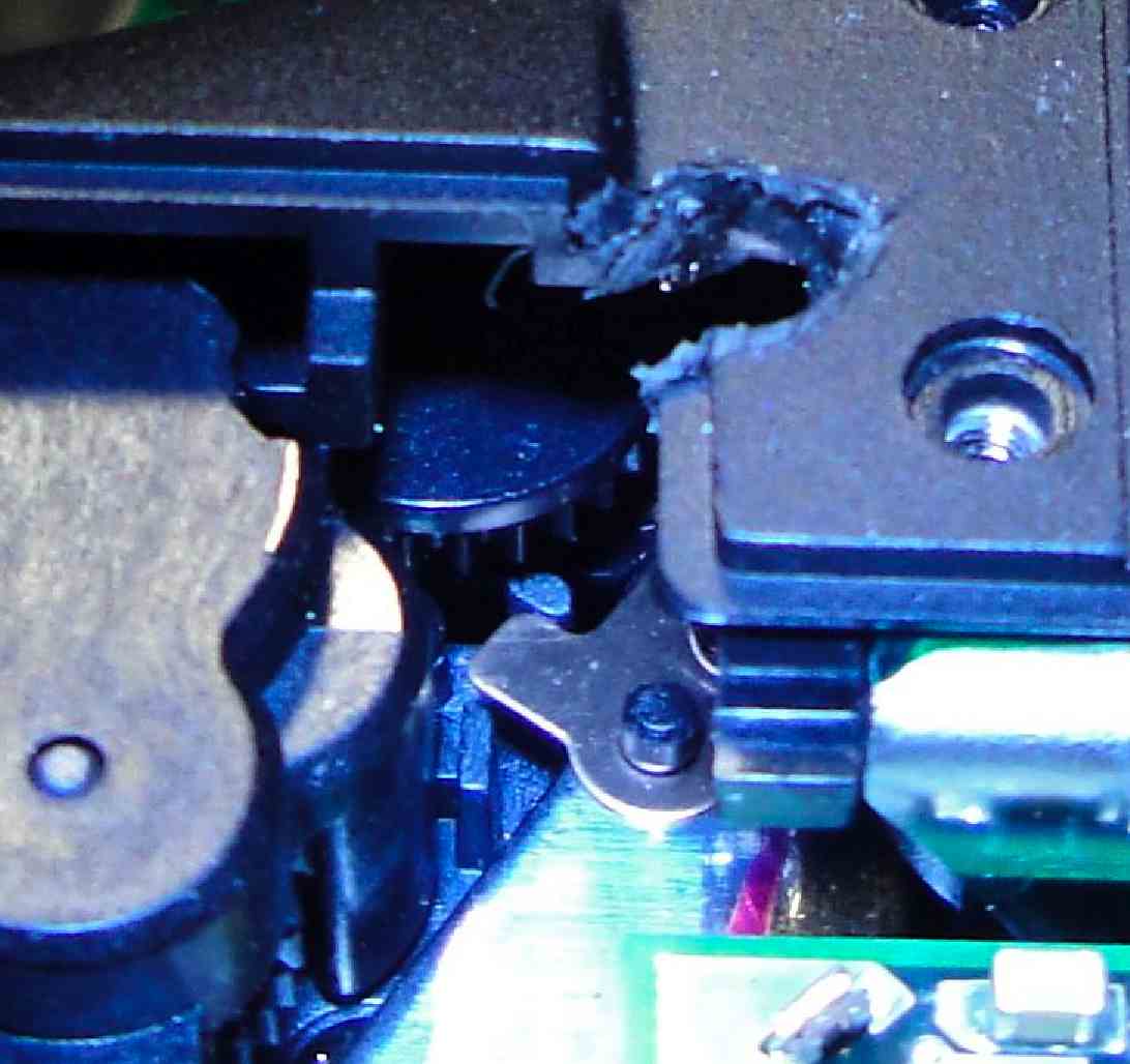 |
Image 6 (Detail) Detailed view of the top positioning screw assembly + hole drilled in the camera case. |
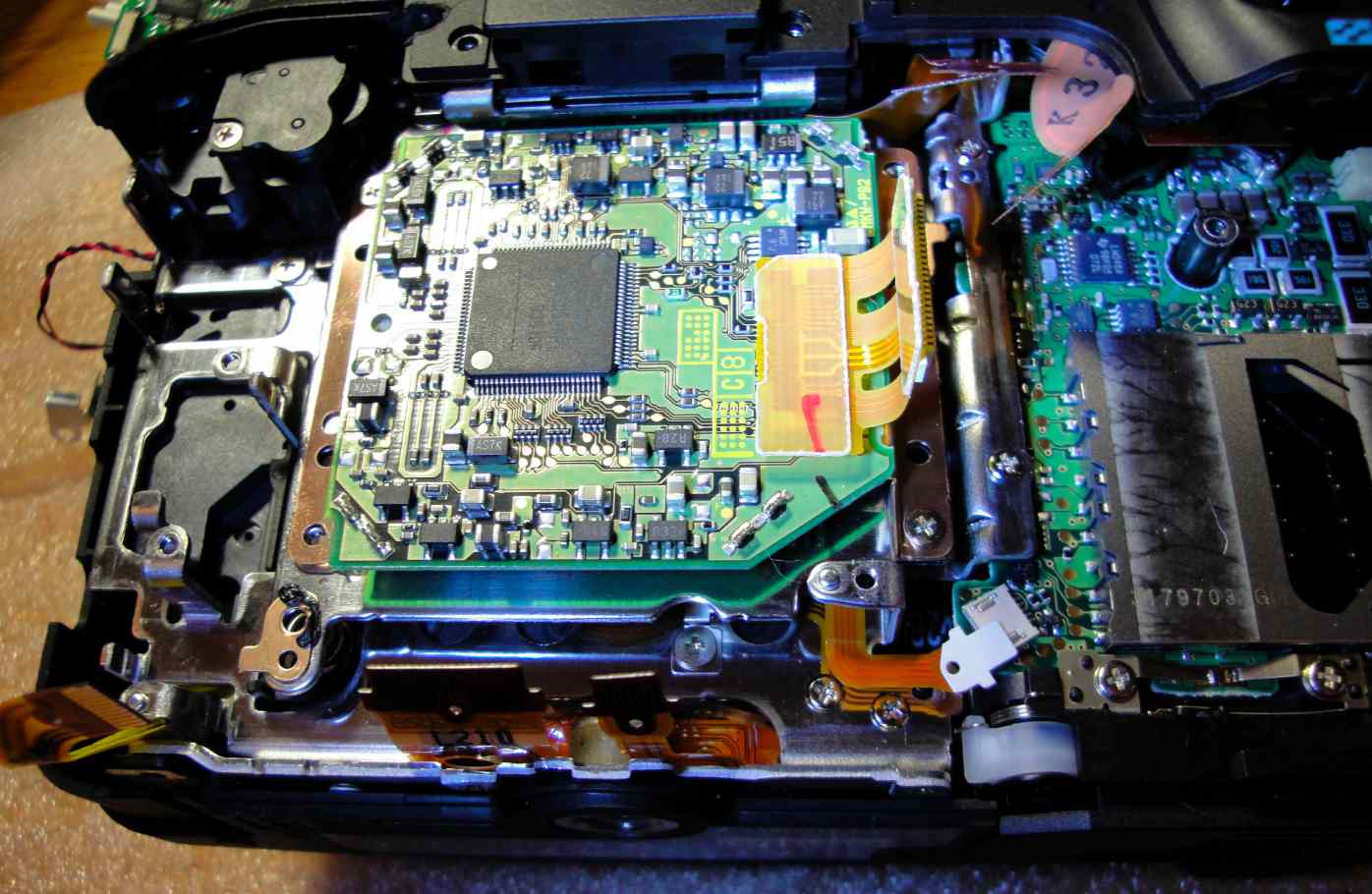 |
Image 7 The 3 screws can now be removed. This view shows the detector unit ready to be removed after the screws have been removed. Make sure you measure the position (depth) of each of the 3 positioning screws before disassembly, as you will need to reproduce it during re-assembly. |
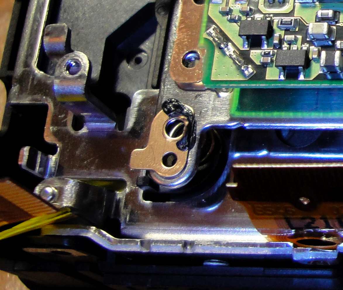 |
Image 7 (detail) This view shows the lower positioning screw location. The screw has been removed, and the spring is visible below the small metal plate. |
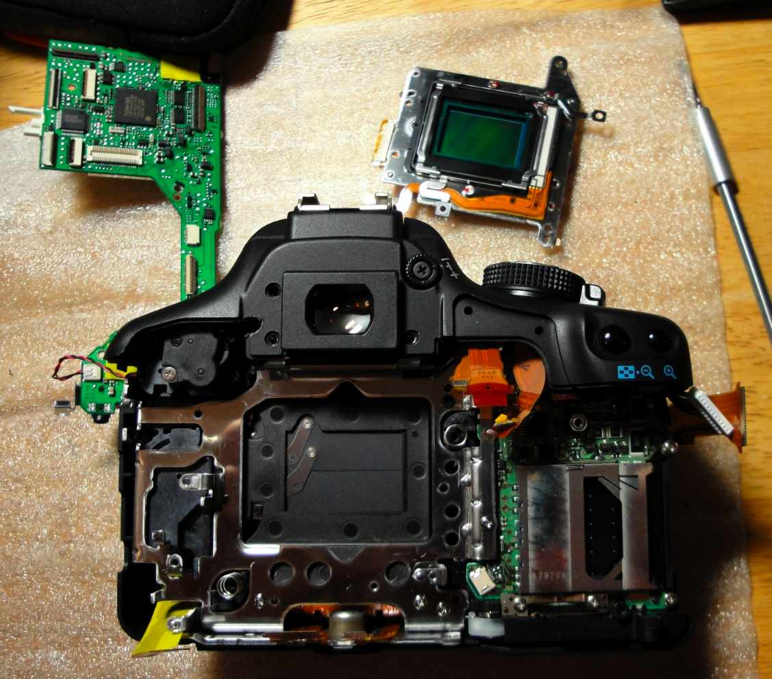 |
Image 8 Detector unit removed from the camera. The detector unit is visible at the top of this image. |
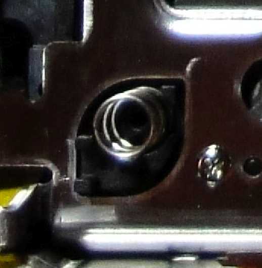 |
Image 8 (detail) This magnified view of the previous image shows the spring for the lower positioning screw. |
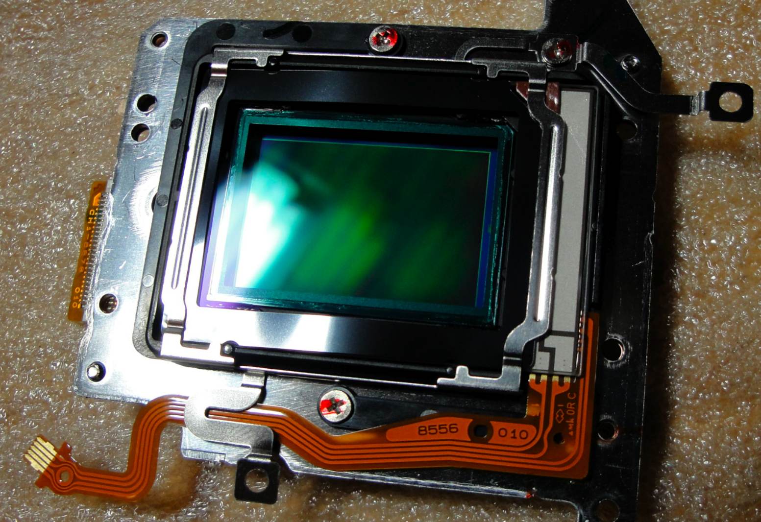 |
Image 9 The detector unit now needs to be disassembled to remove the IR-blocking filter. |
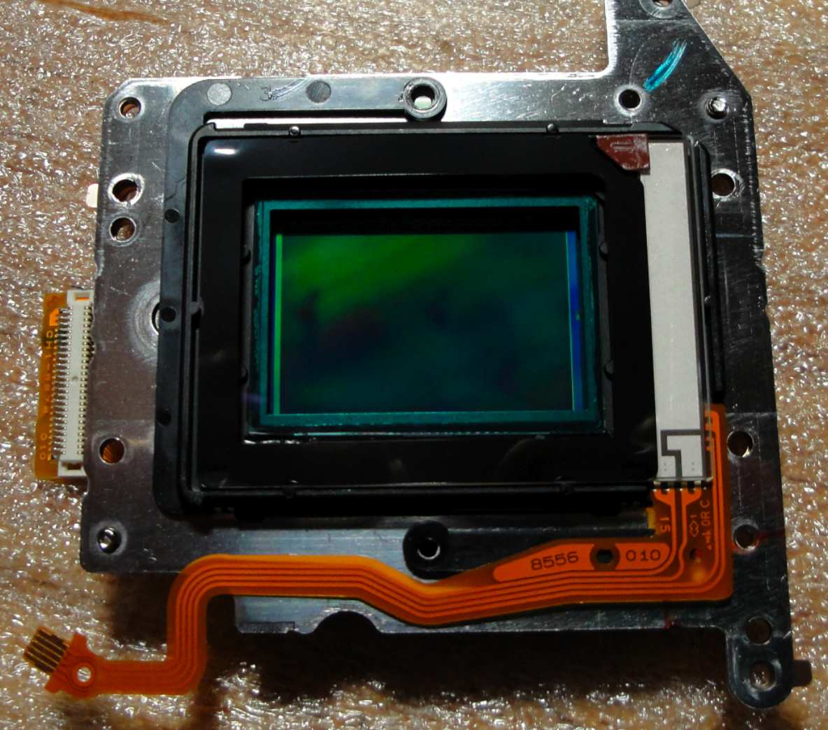 |
Image 10 The first step is to remove the metal frame which is on top of the filter holder. This view shows the detector unit after the frame has been removed. |
 |
Image 11 The filter holder is now removed from the detector unit. The near-IR blocking filter gives the blue color visible in this image. The filter holder also includes the anti-aliasing filter. |
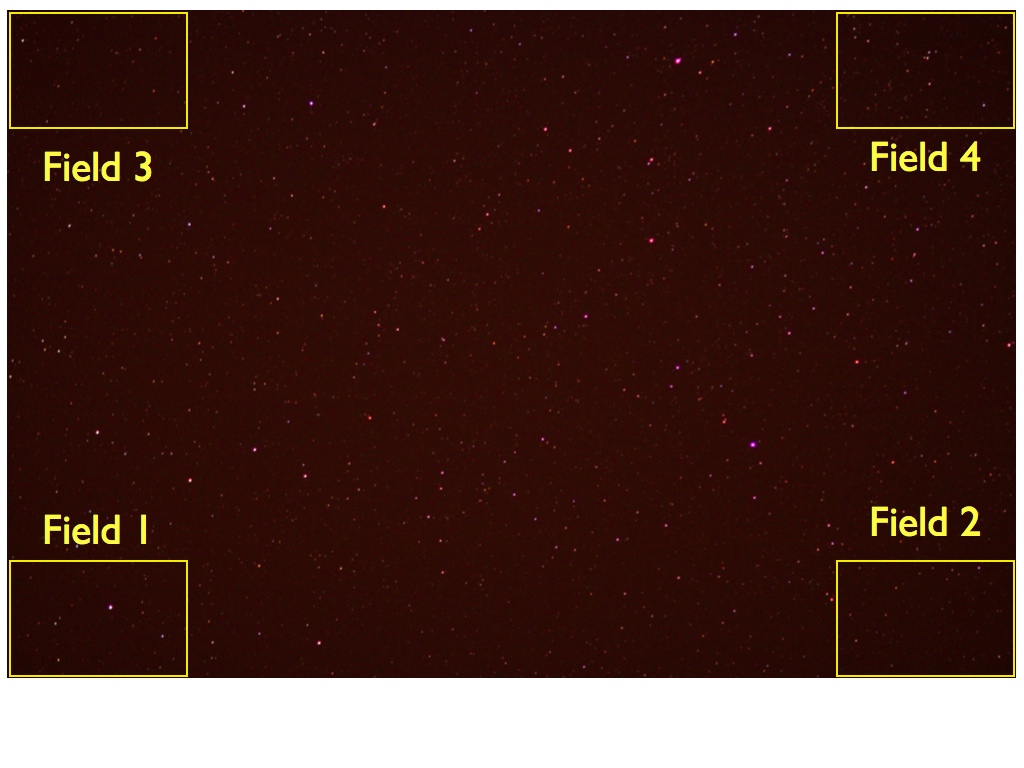 |
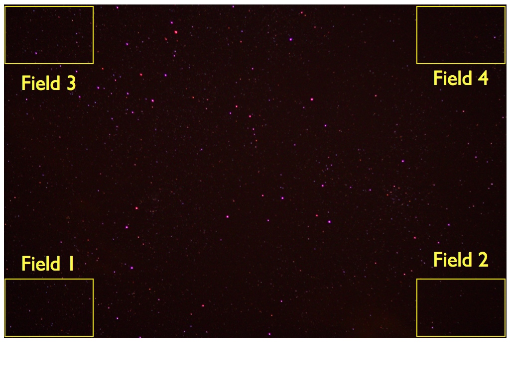
Star field image prior to final detector tip/tilt adjustment Four star fields, at the corner of the full field image, are magnified in the next image to show how PSF sharpness changes across the field. |
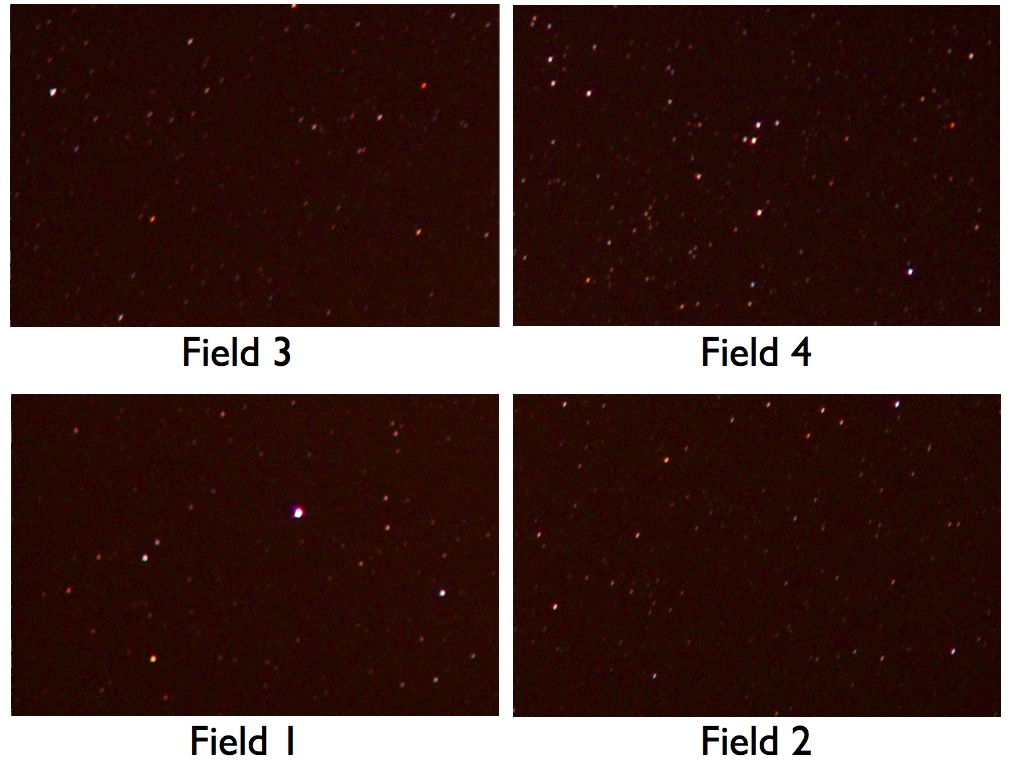 |
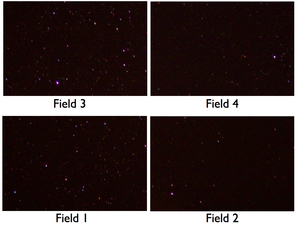
Magnified view of the 4 corners of the image Field 2 is quite sharp but the other 3 fields are out of focus (field 1 is especially far from focus). |
 |
Star field image after final detector tip/tilt adjustment |
 |
Magnified view of the 4 corners The PSF is now sharp (in focus) across the field. |