1. Optical principle

1.1. Overview

As shown in Figure 1-1, the proposed technique uses a wide field diffraction-limited imaging telescope. The central portion of the field is used for coronagraphy and reflected into a coronagraph instrument by a small pickoff mirror. The rest of the field is imaged by a wide field diffraction-limited camera which uses faint background stars as an astrometric reference. By putting dots on the primary mirror, diffraction spikes are created in the wide field astrometric image to provide a suitable reference (linked to the central star) against which the position of the background stars is accurately measured.

Since all astrometric distortions (due for example to changes in optics shapes of M2, M3, and deformations of the focal plane array) are common to the spikes and the background stars, the astrometric measurement is largely immune to large scale astrometric distortions. This concept does not require the ~pm level stability on the optics over yrs which would otherwise be essential in wide field astrometric imaging telescope. The wide field off-axis 1.4-m diameter telescope design shown in Figure 1-1 produces a 0.5 deg x 0.5 deg diffraction-limited wide field image for astrometric measurement and feeds a coronagraph instrument with a 6" field of view extracted in the intermediate focus. This design is inspired from the PECO mission concept study, and is adopted in this document.
Fig 1-1: Example of a telescope architecture for simultaneous coronagraphic imaging and astrometry. The design shown in this figure is for a 1.4-m telescope, and offers less than 10-nm wavefront error in a 0.4 deg diameter field. The telescope primary mirror is covered with small dots. [png]

Fig 1-1(b): Conceptual optical design for the diffractive pupil telescope (DTP). The top part of this figure shows how light is shared between two instruments. The central field containing the bright star and its immediate surroundings is extracted at the telescope’s intermediate focus and fed to a coronagraph instrument for high contrast imaging. The wide well-corrected outer field is imaged onto a large focal plane detector array. Panels (a) to (d) show details of the wide field image acquired in the final focal plane. (a) The wide-field image shows the diffraction spikes introduced by the dots on the primary mirror. (b) The central part of the target image, containing most of the flux, is missing from the wide-field image as it has been directed to the coronagraph instrument. (c) Faint diffraction spikes pave the rest of the field. (d) Faint background stars are imaged simultaneously with the diffraction spikes. While images (a) to (c) are simulated, image (d) was acquired in a laboratory demonstration of the technique. [jpg] [eps]

1.2. Dots on primary mirrors, spikes in the wide field astrometric camera

As shown in Figure 1-2, a grid of dark (non-reflective) spots is physically etched/engraved on the primary mirror. The dots act as a 2-D diffraction grating, and create a set of speckles at large angular separation from the optical axis. These speckles are radially elongated into diffraction spikes by the λ scaling factor in the focal plane. When the telescope is pointed at a bright star, these spikes will be superimposed on a background of numerous faint stars used as the astrometric reference. Precise measurement of the position of the bright central star against this background reference is possible by simultaneously imaging on a diffraction limited wide field camera both the spikes and the background of faint reference stars.
Fig 1-2: Dots on the telescope primary mirror (left) and corresponding on-axis PSF in the wide field astrometric camera. [png]

Formation of spikes

The regular grid of small non-reflective lithographed dots covers a few percent of the surface and is deposited on the front of the primary mirror. The image at the detector is the convolution of the field distribution with the Point Spread Function (PSF) obtained by Fourier transform of the pupil function. Since the Fourier transform of a regular grid of tightly spaced dots is a regular grid of widely spaced points, the monochromatic system PSF is an Airy pattern surrounded by a widely spaced grid of fainter Airy patterns. In polychromatic light, the secondary Airy patterns are radially dispersed, producing long diffraction spikes. This PSF appears at the focal plane for each field object displaced so it is centered where its star is imaged, respectively, modulated in brightness by the source magnitude. The spikes from the background objects are therefore very dim, while the spikes from the host star are much brighter. Light in the central part of the field is directed to the coronagraph, therefore suppressing its bright central Airy pattern while passing its polychromatic diffraction pattern (aka spikes) to the focal plane array used for astrometry.

Fig 1-3: Geometry of the spikes in the wide field of view camera. [png]
The spacing between the spikes, their extent in the focal plane and their overall luminosity can be chosen by appropriate design of the dot pattern on the pupil.

How do the dots help with astrometry ?

The dots serve two purposes:

1.3. Immunity to field distortions

Astrometry with conventional telescopes is hampered by astrometric distortions introduced by the optics and the atmosphere. Any wavefront error introduced ahead or after the telescope's pupil plane creates variations in the plate scale in the focal plane. This effect is known as tilt anisoplanatism, and is the main limitation to precision astrometry on ground-based telescopes (Cameron et al. 2009). In space, with no atmosphere, astrometric distortions are much smaller, but still exist due to bending in optics within the telescope and instrument. Figure 1-4 shows how changes in the telescope's secondary mirror shape produce an astrometric error.

Fig 1-4: Tilt anisoplanatism due to changes in M2's shape creates an astrometric error. [jpg]
The proposed scheme eliminates this problem since the reference pattern (diffraction spikes) is introduced directly on the primary mirror (PM) of the telescope. The dots on the PM act as a diffraction grating creating secondary beams which emerge from the primary mirror with slightly different angles and travel through the optical system up to the focal plane. Light from an off-axis star and light from a nearby diffraction spike go through the same path in the optical system (telescope + instrument) and share the same astrometric distortion. The the anisoplanatism problem is therefore eliminated in the differential spike/backround star astrometric measurement . The proposed scheme is also insensitive to focal plane array distortions, as they will affect equally the background stars and the diffraction spikes. Wavefront errors on the primary mirror do not produce an astrometric error as they are common to both the diffracted beams and the beam from the astrometric reference stars.

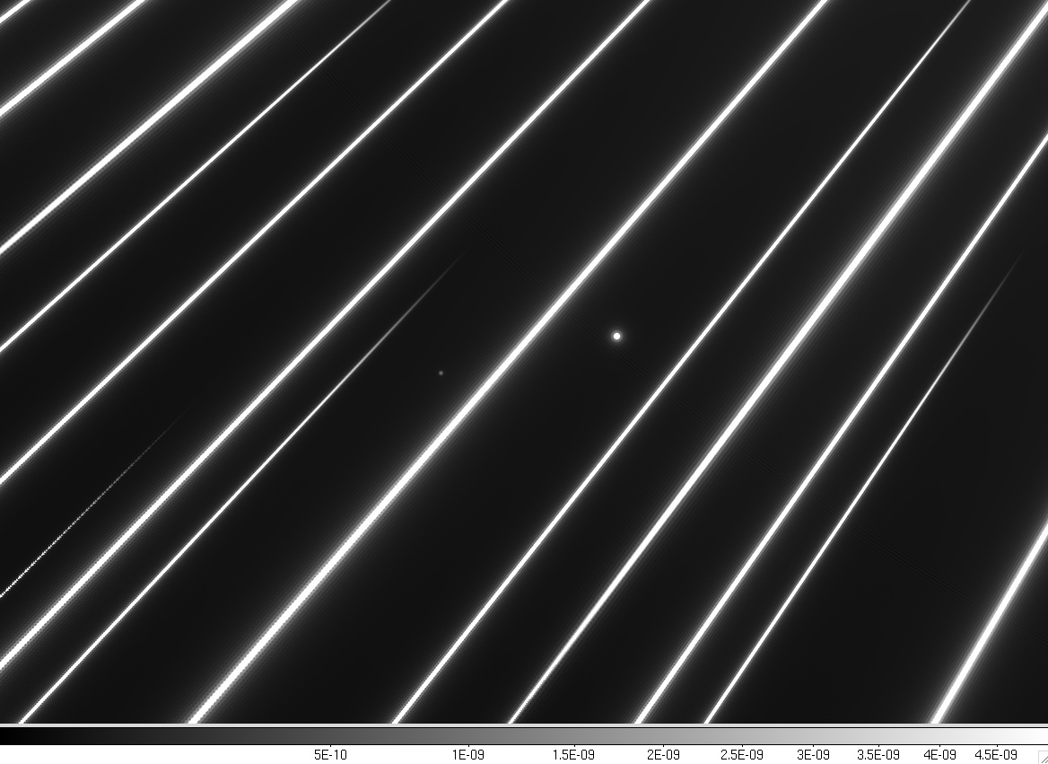
Fig 1-5: Detail of region in the wide field camera (sqrt scale). [jpg]
The diffraction spikes from the central star (located to the upper right of this field) are running across the image, elongated due to plate scale chromaticity. Two fainter background stars are visible. All astrometric distortions (due to optics or detector geometry variations) will affect equally the background stars and the spikes.
Note: While wavefront errors do not directly produce an astrometric error, the changes in the PSF shape they introduce may reduce the precision with which the position of PSFs from the background stars can be measured. This second-order effect is mitigated by using a stable telescope with good pointing accuracy.


For the spikes to encode the same astrometric distortions as the background stars:
  • The dots must cover uniformly the primary mirror, otherwise, changes in PM shape can create a differential motion between the spikes and the background stars. For example, if the dots cover only a zone of the PM, the spikes will move with the average wavefront slope over the area of the PM covered with dots, while background stars will move with the overall wavefront slope over the whole PM.
  • The primary mirror must the aperture stop for the system.
  • There must not be any refractive optics between the primary mirror and the wide field camera detector. Refractive optics have some chromaticity, and the spikes are chromatically elongated (a background star and a spike near it therefore have very different colors, and could see different distortions in a system with refractive optics).
The design studied in this document fullfills these 3 requirements.

1.4. Simultaneous operation with a coronagraph

Since the primary mirror mask is a regular grid containing no low order aberrations, it does not impact high contrast coronagraph observation performed by a separate narrow field instrument, other than a small loss in throughput: as seen by the coronagraph, the pupil is uniformly grey, with a few percent of the light missing (equivalent to a uniform loss in reflectivity in the coating).
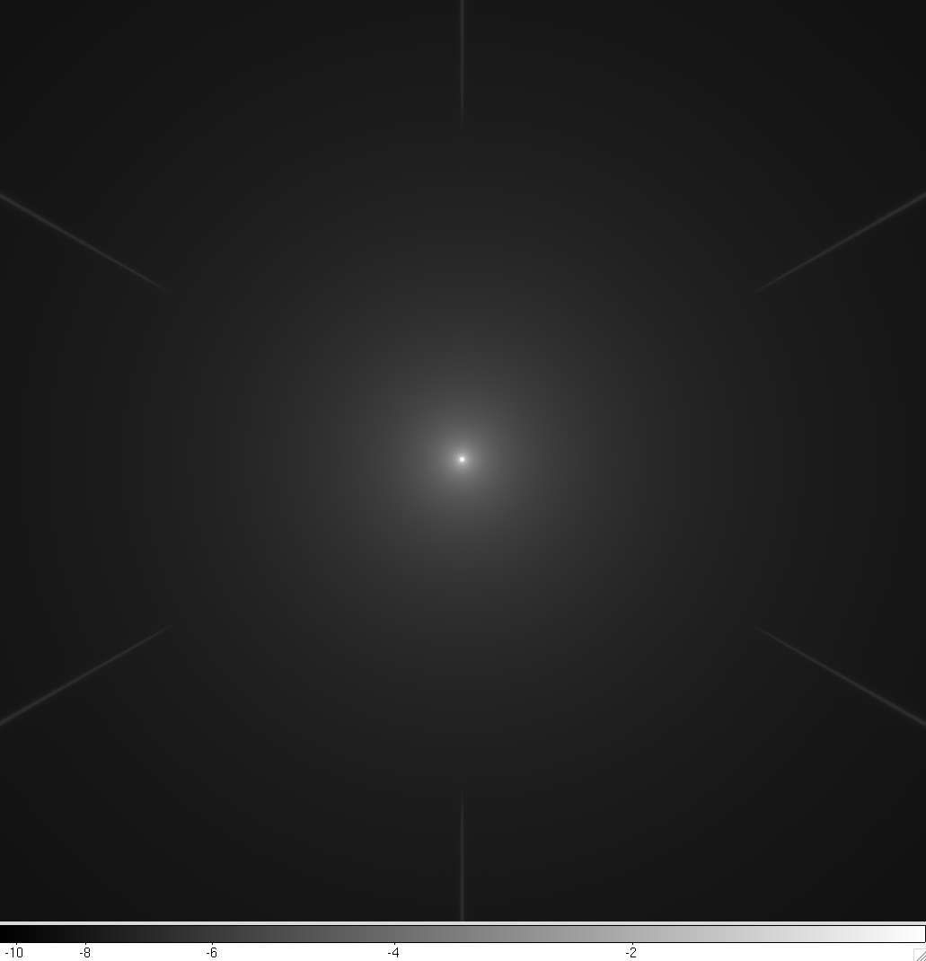
Fig 1-3: Central part of the PSF (log scale, 29 arcsec x 29 arcsec). The PSF is shown here with no coronagraph pickoff mirror. [jpg]
In this configuration, the diffraction spikes do not affect the central 13 arcsec around the optical axis, and have no effect on coronagraphic performance. The halo around the central star is due to the PSF's Airy rings.
The astrometric measurement is a good match to an internal coronagraph:

References