Coherent Differential Imaging
Calibrating speckles using deformable mirror modulation
Coherent Differential ImagingCalibrating speckles using deformable mirror modulation |
 |
Home |
Show content only (no menu, header)OverviewDirect imaging of exoplanet (planets around other stars) is a significant challenge due to the extreme contrast level between exoplanets and the stars they orbit. For example, at optical wavelengths, Earth is about 10 billion times fainter than the Sun. To successfully image exoplanets imaging systems must overcome this high contrast. The current and future instruments designed to image exoplanets therefore include “Extreme Adaptive Optics”: active wavefront control systems that constantly optimize the wavefront in the instrument to maintain high contrast imaging capability. Even with this approach, there is still too much starlight to image the most interesting planets, so calibration techniques are required to separate planet light from the much brighter starlight. Speckle Control and CalibrationDirectly imaging exoplanets requires an optical system able to deliver high contrast images, using wavefront sensing techniques to measure and control starlight in a region of interest, usually located a few diffraction elements from the star. Using focal plane images to sense residual residual errors (refered to as speckle control) is a powerful approach to meet this challenge, as it offers fundamental advantages compared to more conventional pupil-plane wavefront sensing: high sensitivity and absence of non-common path errors. Focal plane images can also be used to separate coherent light (starlight due to wavefront errors) from incoherent light which contains exoplanet images(s), a technique refered to as coherent differential imaging (CDI). 
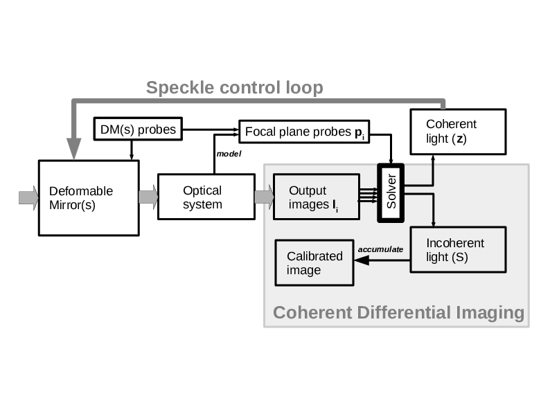
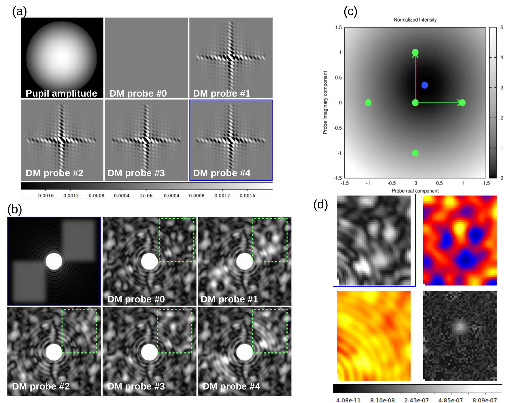
Self-calibrating Coherent Differential ImagingWith Coherent Differential Imaging (CDI), the deformable mirror in the system is modulated to induce a corresponding modulation in the focal plane image speckles. This modulation is measured by a high speed camera, and processed to separate the light that is coherent (starlight) from incoherent light (planet light). The fundamental difference between these two components is that the coherent light reacts to small motions of the deformable mirror by interference, while the incoherent light does not. The technique is described in the simulation shown in Figure 2. To obtain very high performance, even in the presence of calibration errors, the deformable mirror (DM) probes are linear combinations of two master DM probes, This allows the algorithm to fully constrain the incoherent light measurement, yielding photon-noise limited detection of exoplanets in speckles 100x to 1000x brighter, even with large (> 10%) model uncertainties. 
Figure 2 shows Speckle wavefront sensing (SWFS) and coherent differential imaging (CDI) principle. Monochromatic imaging of a faint companion with an apodized pupil is considered here in the presence of wavefront errors.
Page content last updated: 27/06/2023 06:35:52 HST html file generated 27/06/2023 06:34:38 HST |