Near-IR Wavefront Sensor - Technical Description
Upgrade of AO188 to AO3k
The deployment of the NIRWFS happened in phases:
Description of the NIRWFS in Phase II
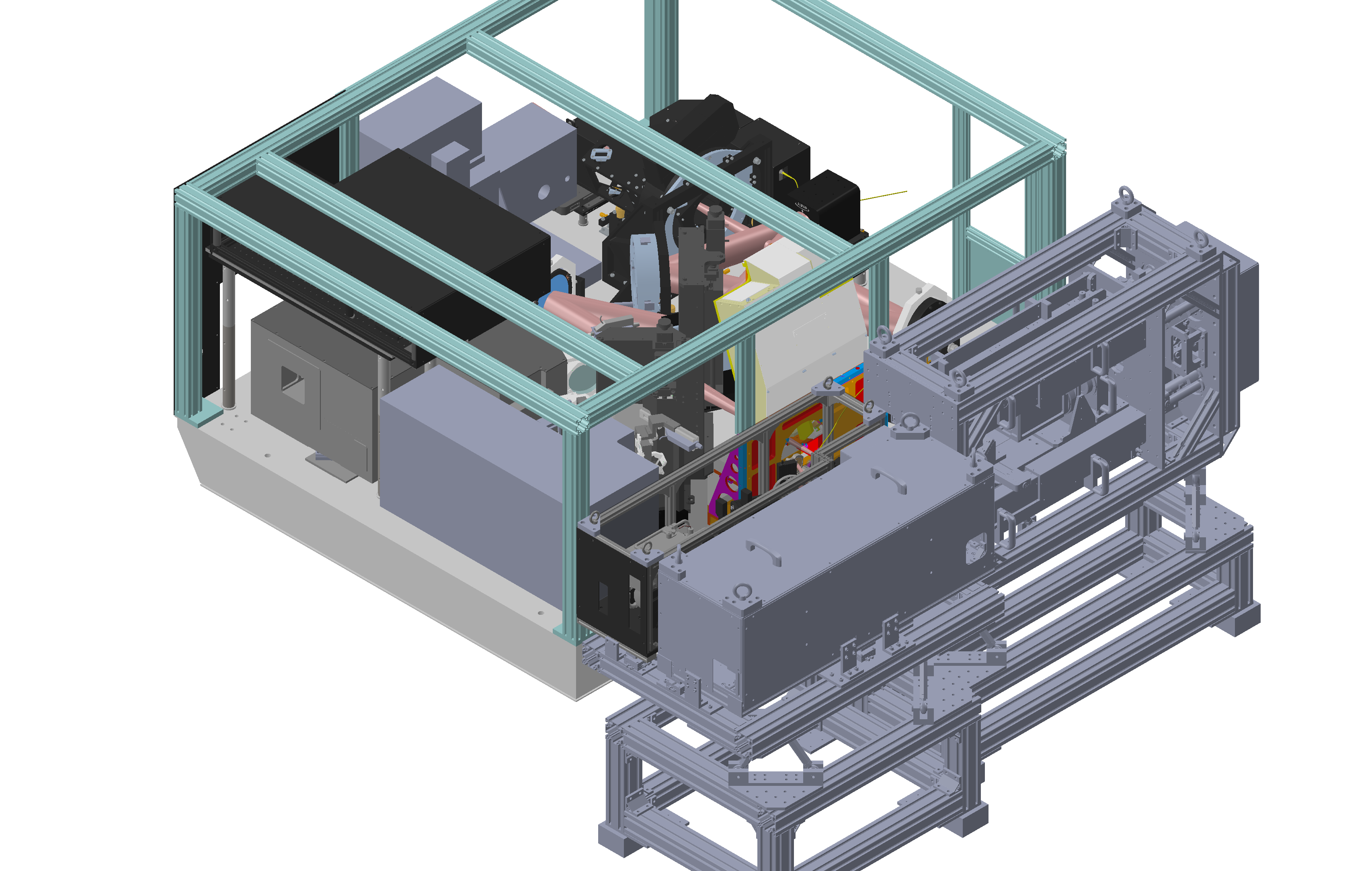
In Phase II, the NIRWFS is installed at the output port of AO188/AO3k, on the LTAO platform. Compared to the phase I design (described below), the phase II design has more space to utilize, allowing to add a few usueful features:
- A dichroic beamsplitter wheel: this motorized wheel allows us to change dichroics when needed, even between targets in the same observation. This is an improvement from the previous design, where only one dichroic was available per observating night.
- A NIR acquisition camera: A small NIR camera is added inside the instrument, to aquire the taregts more efficiently. This camera reduces the overhead between targets, and allows to measure the seeing routinely between targets.
- An adaptive field stop: The NIRWFS struggles to close the loop if one or several other bright stars are preseent in the field of view of the sensor. This field stop will block the light from these stars to reach the camera. Its size can be adjusted depending on the position on the other stars.
- An optical binning mode: Another pupil lens configuration is added to reduce the size of the four pupils on the camera by a factor two. This means that the light is more concentrated on each pupil, which should increase the magnitude limit by almost two magnitudes. However, in this mode, we cannot control as many modes, so the performance will not be as high as the regular PyWFS mode.
 |
|---|
|
|
 |
|---|
|
|
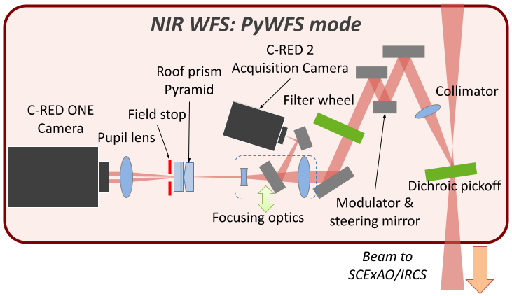
Pyramid Wavefront Sensing (PyWFS) mode
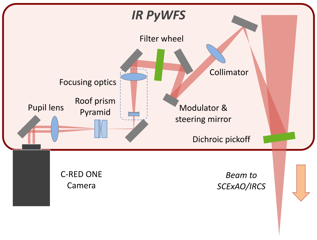
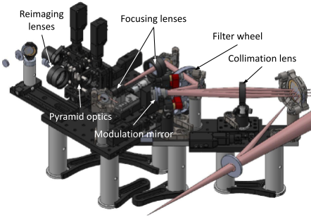
The PyWFS mode is the main mode of the NIRWFS, and the only one offered for Open-Use observations for now. The light coming from the AO3k bench is partly reflected by the dichroic beamsplitter right after the focal plane while the rest of the light goes towards the science instruments. In the wavefront sensor, the reflected light goes through a collimator, with a focal length of 150 mm. A first fold mirror sends the light to a small 1/2 mirror located in a pupil plane, glued on a 3-axis piezo-electric mount use to modulate the beam at several hundred hertz. The mount is itself attached to two rotation mounts used to steer the guide star in the wavefront sensor. The light is then reflected by a second fold mirror and goes through a filter wheel. The filter wheel can select what band or combination of bands go to the camera, with an open slot as the default position. The light is reflected again by a third fold mirror towards focusing optics. The first lens is a concave lens with a 150 mm focal length, identical to the collimation lens. The second lens is a convex lens with a focal length of -50 mm, creating a F/40 beam on the pyramid optics. A pickoff mirror can be inserted between the two lenses to send the light to the NIR acquisition camera, a First Light Imaging C-RED2. The beam on the camera is F/13.9, the same as the output of AO3k. The plate scale is then ~56 mas per pixel, and the field of view is then 36x28 arcsec. With the pickoff out, the light focuses on the tip of the pyramid optics, a double roof prism design. It splits the light into four beams. The new adaptive field stop is placed right after the prisms, as it was not possible to put it in the focal plane. Finaly, a 80 mm pupil lens image the four pupils on the First Light Imaging C-RED ONE camera. A second set of lenses (two 100 mm lenses) can be inserted instead, for the optical binning mode.
 |
|---|
|
|
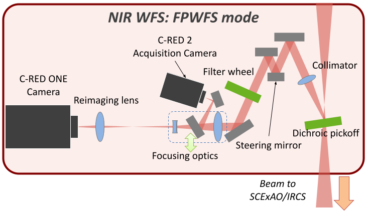
Focal Plane Wavefront Sensing (FPWFS) mode
This mode is still in an experimental phase, so not avaiable for open-use observations. The NGS is reimaged on the camera, with a small defocus.This creates a phase diversity that allow us to control low-order modes. This could be used in the future to extend the range of magntiudes available, with limited performance, since we will not be albe to correct as many modes as the PyWFS. It could also be used as a truth hWFS for the new LTAO instrument.
 |
|---|
|
|
In this mode, the pupil lens is swapped with a reimaging lens, the pyramid optics are removed from the beam, and the distance between the focusing lenses is changed to focus the light on the camera. A Small defocus can be added for wavefront sensing.
If the source is focused on the detector, this mode can be used to look at the image quality (in open-loop), measure the seeing or calibrate the radius of the modulation applied for the PyWFS mode.
Dichroic beamsplitters
Several beamsplitters are available, depending on the instrument and science case. Since the flip mount only accommodates one optic at a time, a choice has to be made before each observing run on what beamsplitter to use. Once the Nasmyth Beam Switcher is installed, version 2 of the NIRWFS will move to the LTAO WFS platform, and we will have enough space to include a mechanism (wheel or linear actuator) to switch between the different options.
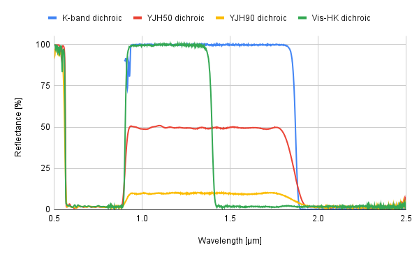
- K-band dichroic: DBS originally designed for IRCS, but can also be used for high-res K-band CHARIS observations. It sends 100% of y-, J- and H-band to the NIRWFS, 100% of K-band to the science instrument.
- YJH50 dichroic: This DBS is sending 50% of y-, J- and H-band to the NIRWFS, 50% to the science instrument, in addition to 100% of visible light (600-900 nm, for SCExAO only) and K-band.
- YJH90 dichroic: This DBS has the same characteristics as the previous one, but sending only 10% of y-, J- and H-band to the NIRWFS, 90% to the science instrument. This is the most efficient option for brighter targets, without compromizing too much the efficiency of the science instrument.
- Vis-HK dichroic: This DBS is sending 100% of y- and J- band to the NIRWFS, 100% of the visible (for SCExAO only) and H- and K-band to the science instrument. This option requires sources bright enough in J-band, instead of H-band.
Camera Settings
The default window size is 160x160 pixels, although the full frame (320x256 pixels) could be used for the FPWFS mode. With a 160x160 pixel window, the acquisition runs at a maximum frame rate of 9.8 kHz. We can then use the camera in correlated double sampling (CDS) mode or non-destructive read (NDR) mode to get the optimal noise level and speed, between 1 and 4.9 kHz depending on the target brightness. CDS is the default mode, since the camera integrates during a whole cycle of the modulator. If the modulation is not used, then NDR could be used. The detector gain can also be adjusted between 1 and 121 (max) for bright targets.
The C-RED ONE camera is used in Correlated Double Sampling (CDS) mode, where the sub-frame is read immediately after a frame reset, then reset and read again. The result is the difference between the frame before the reset and the previous one just after the reset. The sub-frame used is 160x160 pixels, with a read time of t_read = 102 μs. So if we program the CDS mode to run at a frequency F_CDS, then the actual integration time t_int will be:
t_int = 1/F_CDS - t_read.
In that case, we do not want the modulator to be synchronized with the CDS reads, otherwise we would
lose a fraction of the rotation during the actual integration time. Therefore, the modulation
frequency F_mod is set to
F_mod = 1/t_int = F_CDS/(1-F_CDS*t_read).
Integration time, modulator frequency and maximum modulation radius for various loop frequencies
The Table below presents the integration time, modulator frequency and maximum modulation radius for various loop frequencies. The maximum frequency for CDS mode and the desired sub-window is 4.9 kHz, at which point the duty cycle drops to 50%. The readout scheme creates a rolling shutter effect linked to the duty cycle that is out of the scope of this page, although we will probably always be at or below 2 kHz, where this effect will not impact us too much.| Integration time, modulator frequency and maximum modulation radius for various loop frequencies | |||||
|---|---|---|---|---|---|
| CDS frequency [Hz] | 500 | 750 | 1000 | 1500 | 2000 |
| Actual integration time [ms] | 1.898 | 1.231 | 0.898 | 0.565 | 0.398 |
| Modulator frequency [Hz] | 526.9 | 812.1 | 1113.6 | 1771.0 | 2512.6 |
| Maximum modulation radius [mas] | 250 | 190 | 145 | 60 | 40 |
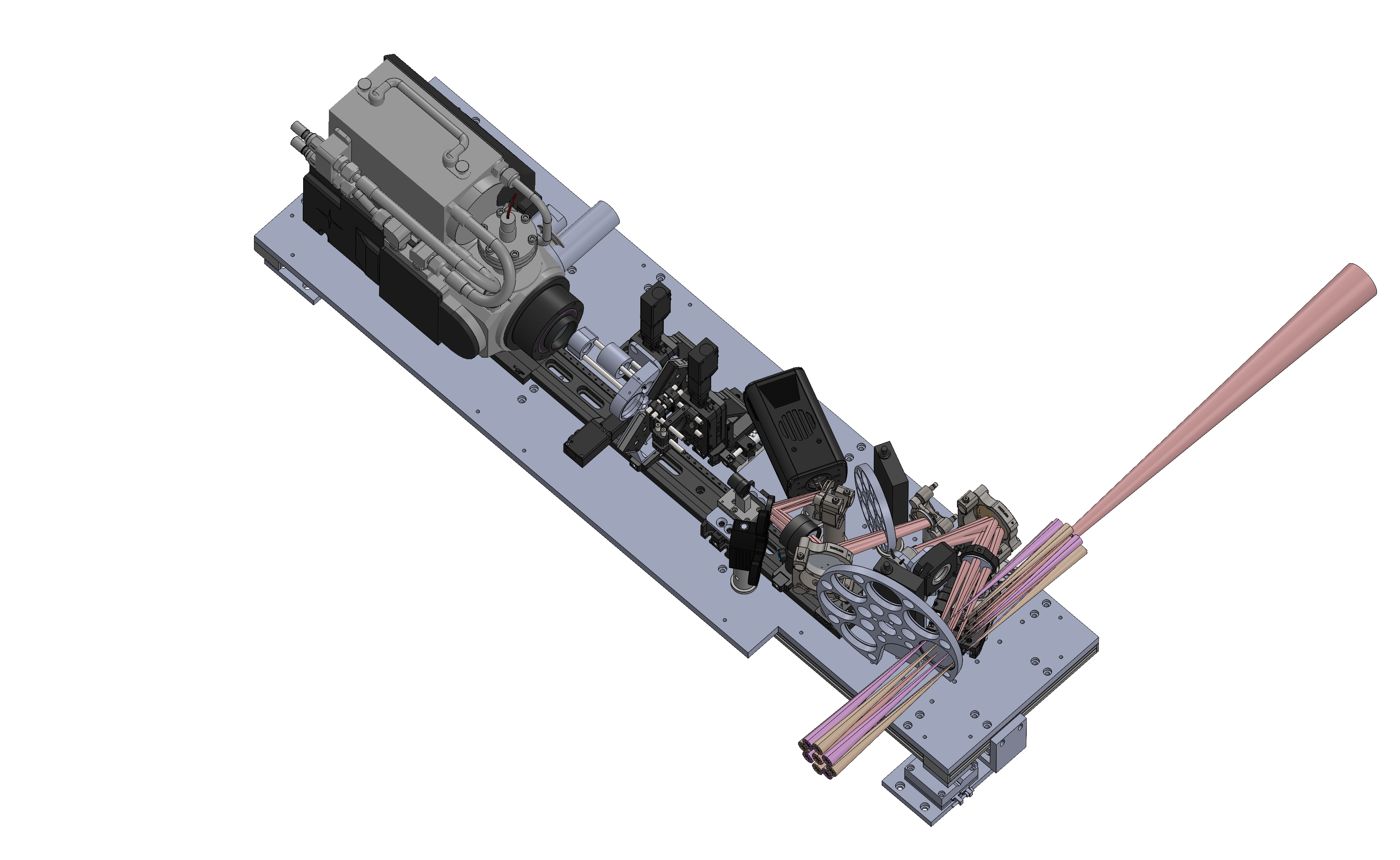
Description of the NIRWFS in Phases Ia & Ib
In Phase I of the deployment of the NIRWFS, the optics fit inside AO188, while the C-RED ONE camera was mounted on the side of the instrument. This was due to a lack of space inside AO188. The camera had to be removable, since a collision is possible with SCExAO's own C-RED ONE camera used for the FPDI mode. Therefore, in phase I, it wwas not be possible to have both cameras at the same time. Figure 5 presents the position for the optics and the camera. The dichroic beamsplitter sending some light to the NIR PyWFS was designed to be compatible with science observation with IRCS, especially K-band spectroscopy. 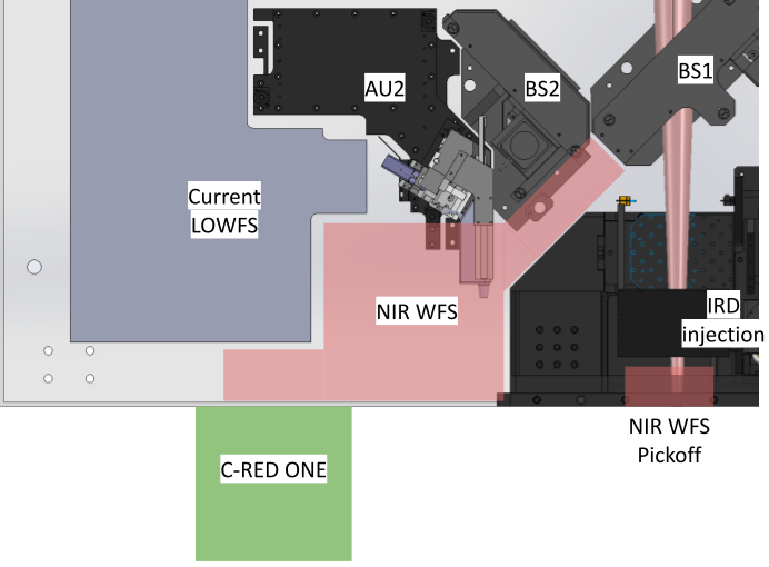 |
|---|
|
|
Optical path
This mode uses a pyramid-type optics to split the focal plane light into four, and reimage the four beams in the pupil plane. The PyWFS is used to control the wavefront with the deformable mirror of AO188/AO3k.
 |
|---|
|
|
A dichroic beamsplitter pickoff is placed in the output beam of AO188, selecting some of the light that goes to the NIRWFS. The light is reflected by a first fold mirror, then collimated by a collimation lens. The pupil of the telescope is then reimaged on a small mirror acting both as the modulator (using piezo actuators to move the PSF in a circular motion around the tip of the pyrmaid optics) and the steering mirror to control off-axis NGSs. The light is then reflected a couple more times, goes through a filter wheel that selects which band will be used, then goes through compact focusing optics, composed of a converging and a diverging lens. Another fold mirror sends the focusing light on a pair of roof prisms, acting as a pyramid optic. This is the same concept validated by the PyWFS of SCExAO. Once split into four beams, a pupil lens (and a last fold mirror) reimages the pupil on the detector of the C-RED ONE camera.
A pupil viewing mode is also available (in open-loop), simply by removing the pyramid optics from the beam.
NIRWFS dichroic beamsplitter
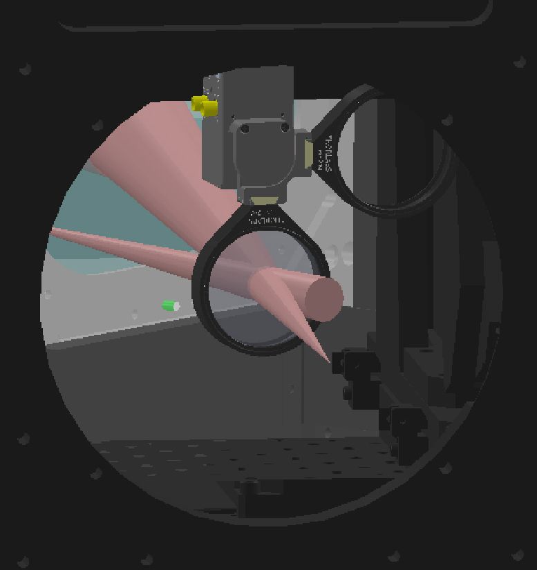
The dichroic beamsplitter (DBS) for the NIRWFS is placed at the output of AO188, inside a flip mount attached upside-down. It is placed at a shallow angle of 12 degree to send the light to the NIRWFS. The flip mount allow to move the beamsplitter out of the way without colliding with the IRD injection, but the flip mount can also be removed entirely thanks to locating pins.
|
|---|
|
|
Core optics
The core optics were designed to fit the narrow space available inside AO188. Due to the small field-of-view required for the instrument, we can have a small beam size and small optics. This is crucial to have the propoer modulation for the PyWFS. Indeed it is harder to move a 1-inch mirror at kilo-hertz speed than a ½-inch mirror. The compromize is then that the capture field-of-view is not big: we can only use off-axis NGs up to 14" from the target of interest.
|
|---|
|
|
The optics are mounted on two platforms, a narrow platform and a large plateform. The narrow platform contains:
- A first 2-inch fold mirror.
- A 150 mm collimation lens. The lens is on a motorized translation stage to change the focus.
- A ½-inch modulation mirror where the pupil is reimaged. The modulation mirror is on a motorized tip/tilt mount, to use off-axis stars as guide stars.
- A second 1-inch fold mirror.
The large platform contains the rest of the optics :
- A filter wheel that can reduce the bandwidth of the WFS. It contains 3 band filters (y, K or H-band), 2 dual-band filters (y+J and J+H) and an open slot.
- A third 1-inch fold mirror.
- A converging+diverging lens combination allows one to focus on the pyramid optics with the right F/ratio while keeping a compact configuration. The diverging lens is on a motorized mount to change the distance between the lenses (therefore the F/ratio), while the combination is on a motorized translation stage to focus precisely on the tip of the pyramid optics.
- A fourth 1-inch fold mirror.
- The dual roof prism pyramid optics splitting the light for the wavefront sensor. The optics are on a motorized vertical translation stage, which allows to move it out of the way for a focal plane imaging mode.
- Two lenses on a motorized X/Ystage: one 80 mm lens reimaging the 4 pupils on the detector for the PyWFS mode, and one 150 mm lens reimaging the focal plane for the FPWFS mode.
- A fifth 1-inch fold mirror.
Camera
|
|---|
|
|
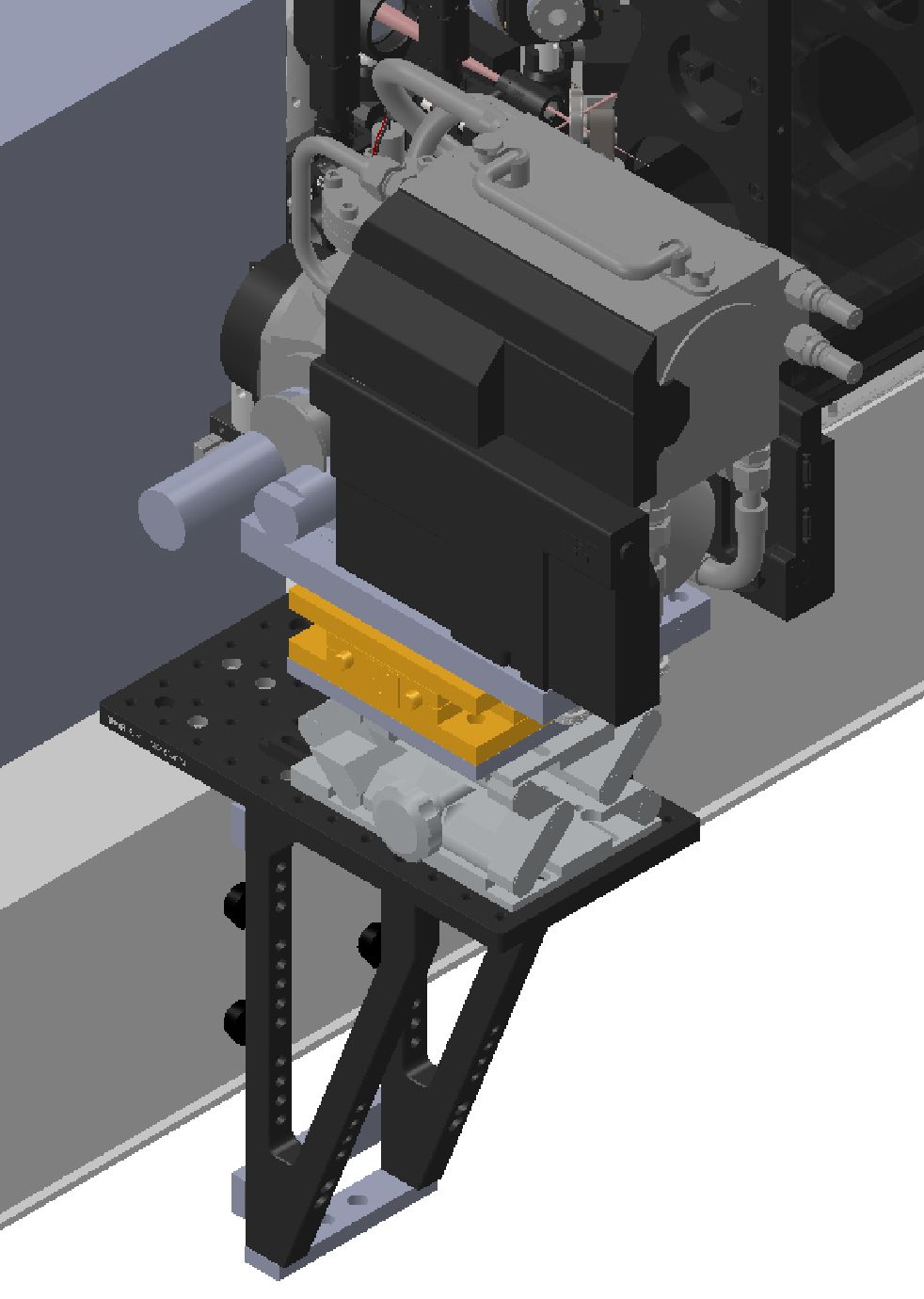
The camera is mounted on a platform hanging on the side of AO188, supported by brackets resting against the side of the AO188 bench. This was the only possible solution due to the optical path, the lack of space inside AO188, and the constraint on the shared use of the camera with SCExAO FPDI mode (although this constraint will not exist once the Nasmyth Beam Switcher is installed in Phase II). For alignments, the camera is mounted on a high-load lab jack for vertical alignment, as well as a high-load 2-axis stage, for horizontal and focus alignment. This is a duplication of the alignment mount of the FPDI, which performs very well.