
High-Order Visible AO loop
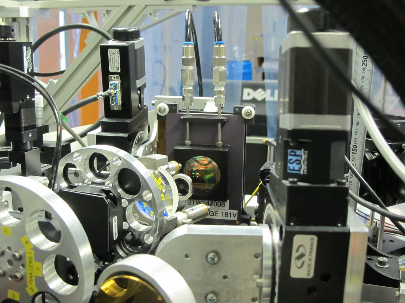
An image of the 2000 element deformable mirror used in SCExAO.
High-order wavefront sensing and correction is the key feature of the SCExAO Project. High order wavefront correction, or "extreme AO" requires a deformable mirror with many actuators across the pupil to correct for high spatial frequencies. In addition, it requires the control loop to run much faster than the coherence time of the atmosphere (~1 ms/1 kHz). For this reason we use the Boston MicroMachines 2000 element MEMS-based deformable mirror. For full details about the deformable mirror please see our publications.
One interesting feature of the DM is that it should not be operated in a high humidity environment as this causes advanced ageing. In order to accommodate this we have developed a dry air supply circuit. This circuit is interlocked such that the DM electronics are shut off if the humidity goes above 15% and or the pressure in the line deviates from the nominal setting of 0.4 psi. Please see this document for further details about the interlock system.
The other major aspect to high order wavefront correction is sensing. For this we utilize a pyramid wavefront sensor. This sensor operates in the visible between 600 and 900 nm. We have recently begun to use a pyramid prism which replaced the micro-lens arrays used in the past. The concept is to place the vertex of the pyramid/micro-lens array in the focal plane to create 4 distinct images of the pupil from each sector of the focal plane image. As each pupil image does not have all the Fourier information from the entire PSF, phase errors manifest as amplitude errors which are detectable by the sensor.
Since it is quite difficult to obtain a pyramidal optic we chose a non-traditional approach to build our PyWFS. The concept we use utilizes two roof prisms oriented so that the roof vertices are orthogonal to one another (one is horizontal and the other is vertical). This concept is shown on the Figure below, on the right.
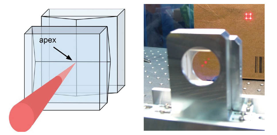
Left: Schematic of the roof prism pyramid optic concept ; Right: Roof prism assembly diffracting a collimated beam into 4 beamlets.
The space between the vertices is very small (20-50 µm) and as close as possible to the focus of the beam to minimize the affect of diffraction. The assembly can be seen on the right of the above figure, before installation in SCExAO.
Images of the 4 pupils (see below)) are then acquired by a photon counting EMCCD (OCAM2k - FirstLight Imaging) with a 3.5 kHz binned frame rate, negligible latency and a 0.3e- read-out noise at a gain of 600x.
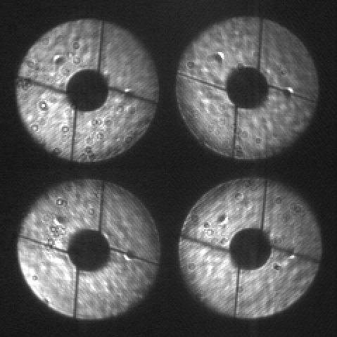
Pyramid wavefront sensor image with the Pyramid prism. The pupil image is now very clean and sharp. Note this is with 9 λ/D modulation radius.
We also included a fast tip/tilt mount to modulate the pyramid response that can be run up to 10 kHz but amplitude of modulation drops off at higher frequency.
The PyWFS works on-sky and typically corrects up to 1200 modes improving the PSF stability for science observations (see images on our internal science camear below, with and without the PyWFS loop closure).
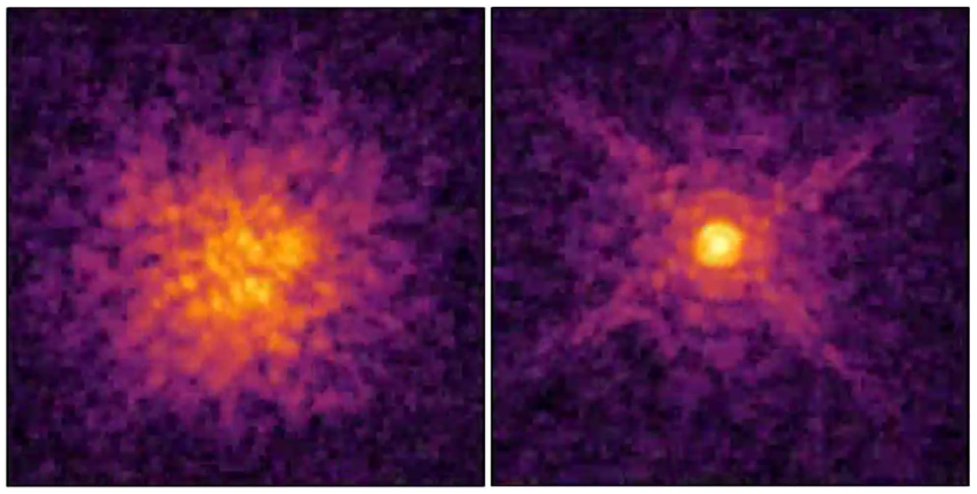
Left: Internal science camera with the PyWFS loop open ; Right: Internal science camera with the PyWFS loop close. Full video available on this link
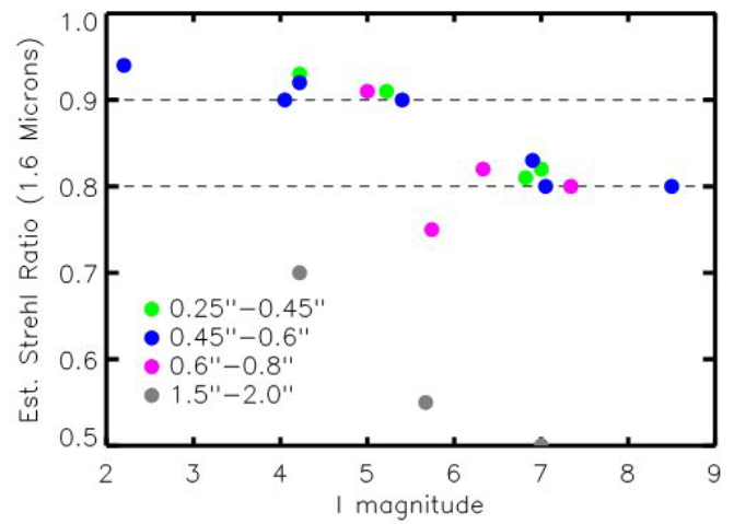
Strehl measurements regarding the magnitude of the star are showed on the next graph:
Left: Internal science camera with the PyWFS loop open ; Right: Internal science camera with the PyWFS loop close.
The importance of tip-tilt correction
Because it is optimized for the detection of companions at low angular separations, a high-performance coronagraph such as the PIAA is pushed to become highly sensitive to low-order aberrations, and especially pointing errors. Indeed, for angular separations close to 1 λ/D, the signal created by a small (<< λ/D) pointing error can perfectly mimic the one of a high-contrast companion that would be located at a larger separation. Since the coronagraph is designed to transmit the signal of such companions, it will transmit the pointing error signal. The SCExAO system therefore includes a robust and accurate wavefront sensor to measure the tip-tilt as well as defocus, so-called Coronagraphic Low-Order Wavefront Sensor (CLOWFS).
CLOWFS uses the light reflected by the focal plane mask located after the apodizer (c.f. Figure). However, instead of reflecting all the on-axis stellar light, the central part of the mask is opaque and only a reflective annulus around this central part sends light to the CLOWFS camera, which acquires a defocused image of this annulus. Discarding the central part of the light rejects a lot of flux that contains very little signal. In a manner that is reminiscent of Schlieren photography or the Foucault knife-edge, this central dark zone makes tiny changes in the wavefront produce macroscopic changes in the CLOWFS image. For wavefront aberrations smaller than 1 radian, the CLOWFS image is a linear function of the wavefront aberration modes. In the lab, CLOWFS has demonstrated very good performance, successfully helping to stabilize the tip-tilt with residuals approaching 10-3 λ/D.
The Lyot-based CLOWFS
For phase mask based coronagraphs like the PIAA, PIAACMC, 4QPM, 8OPM and Vortex versions, the light is not reflected but transmitted by the focal plane mask and hence the original CLOWFS concept outlined above does not apply. Instead we have adapted our CLOWFS so that light diffracted by the focal plane mask is reflected at the Lyot-stop towards the LOWFS camera. The beam is refocused onto the camera which is slightly defocused in a manner similar to the original concept.
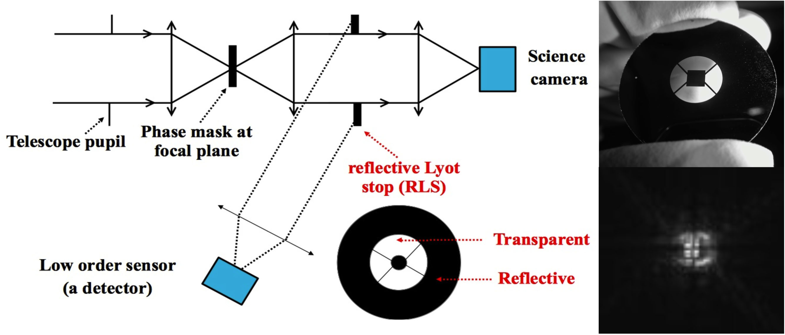
The Lyot-based LOWFS concept. An image of a reflective Lyot-stop mask (chrome plated).
A reference image
of the PSF with the 4-quadrant phase mask in the focal plane.
The Lyot-based LOWFS has been tested on the first 3 modes (tip/tilt and focus) in the laboratory. Here is a video of the lowfs loop closing on the coronagraphic PSF generated by the vortex coronagraph. The video shows a constant tip/tilt modulation being applied in a circle while simultaneously the turbulence applied is varied (to simulate varying degrees of seeing). Keep an eye on the two images to the bottom right the left of which shows the image the LOWFS sees and the right the internal science camera. Also note the tip/tilt residual graph improvement when the loop is closed and tuned.
File ./020instrument.web/010wfsc.web/content.html last modified 25/07/2023 20:17:00 HST