The light reflected off the slit is observed by a camera called the slit
viewer (SV). With this camera the object to be observed with the
spectrograph is identified and then introduced to the slit. On a clear
dark night, a point source with R ~ 18 magnitude is detectable.
Objects as bright as V = 1 mag do not saturate when viewed with a neutral density (ND4)
filter. Two other filters for the V and R bands are also available, as well as
a BP530 filter (central wavelength: 529nm, FWHM: 39nm), optimized for I![]() absorption wavelengths.
absorption wavelengths.
The quality of mechanical (open) tracking of the telescope is not sufficient for long exposures, hence a guiding system should be used in most circumstances. Currently, the guiding can be done either in the on-slit mode directly on the science target with the SV (preferred), or on a separate guiding object with the AG.
Guiding using the target itself (observed in the slit viewer) was introduced quite recently and is now the preferable mode. The current system works well on objects as faint as 20th magnitude with 5 sec exposure time.
With the AG unit, the guiding is done using a guide star approximately
1 arcmin from the target. The guide star is automatically
selected when the position of the target is given to the telescope
control system. With the current system a star brighter than 15th
magnitude is acceptable as a guiding object (this will be improved in the future).
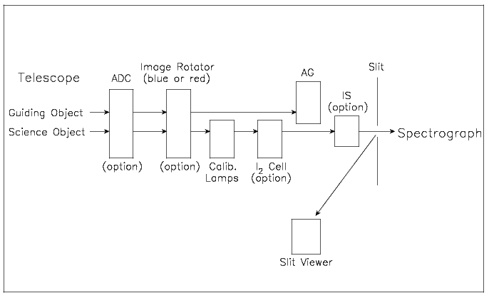
As shown in Figure ![[*]](crossref.png) , the AG probe is located behind the
image rotator, the position of the guiding object against the target
is fixed when image rotator is used. On the other hand, the field of
view rotates when image rotator is not used, and the change of
the position of guiding object against the target is compensated by
the rotation of the AG probe around the beam of the target. However,
the quality of the driving (rotation) of the AG probe is not perfect,
and the error of the guiding without image rotator is worse than that
with rotator: the error is about 1 arcsec per hour when the field
rotation is fast. The correction of the guiding position is possible
during the exposure. But the quality of the guiding with image rotator
is still better than that without rotator, so the observation with
image rotator is recommended even for point sources when the guiding
quality is quite important.
, the AG probe is located behind the
image rotator, the position of the guiding object against the target
is fixed when image rotator is used. On the other hand, the field of
view rotates when image rotator is not used, and the change of
the position of guiding object against the target is compensated by
the rotation of the AG probe around the beam of the target. However,
the quality of the driving (rotation) of the AG probe is not perfect,
and the error of the guiding without image rotator is worse than that
with rotator: the error is about 1 arcsec per hour when the field
rotation is fast. The correction of the guiding position is possible
during the exposure. But the quality of the guiding with image rotator
is still better than that without rotator, so the observation with
image rotator is recommended even for point sources when the guiding
quality is quite important.
The ADC is not applicable to UV observation due to its low efficiency in that wavelength range. The guiding taking into account the atmospheric differential dispersion between the observing wavelength (on SV) and the guiding one (on AG) is available for UV observation without ADC. The guiding position cannot automatically be corrected corresponding to the change of the atmospheric differential dispersion during exposure. But the guiding position for the atmospheric dispersion at the exposure center can be given.
In order to control the position angle of the slit image, two image rotators for blue and red regions are mounted in front of the slit. The direction of slit image is not essential for the observation of point sources, but the image rotator can be useful for observation of objects with large atmospheric dispersion.
The ADC is useful when the elevation of the object is low. Since the
ADC is designed for observations with elevation higher than 30
degrees, the quality of the correction of atmospheric dispersion is not
good for objects with lower elevation (the correction is fixed to that
for the elevation of 30 degree). The efficiency of the ADC is high for
wavelengths longer than 3600 Å, but it steeply decreases at shorter
wavelengths (see Section ).
A halogen lamp and two hollow cathode lamps (Th-Ar and Fe-Ar) are available for flat-fielding and wavelength calibration, respectively. One ND filter and two color filters are mounted in this system.
The Th-Ar line atlas for the wavelength calibration of HDS spectra is available here.
In order to collect more photons while keeping high spectral resolving power in the same time, one of the three image slicers (IS) can be used. The IS reformats the 2D-image of an entrance aperture (different for each slicer) in the F/12.6 focal plane of the telescope into a series of narrow slits, which is imaged on the spectrograph entrance slit. The currently available slicers allow for the effective resolving power of 110,000 (IS#1), 80,000 (IS#2) or 165,000 (IS#3). With respect to a narrow slit giving a comparable resolving power, more light is collected and the final S/N of the spectrum is substantially higher.
Each of the slicers is put into the optical beam manually. Additionally, the focus of the telescope changes and must be adjusted, thus the IS should not be changed, removed or inserted during the night. Guiding should be performed directly on the science target with the SV.
For more details see Tajitsu
et al. (2012), Section or this
webpage.
This instrument is used for the accurate measurement of radial velocities
for astronomical objects. By inserting the I![]() cell into the optical path, the
absorption lines of I
cell into the optical path, the
absorption lines of I![]() molecules are superposed on the spectrum of
target objects in the wavelength range ~5000 - 6500 Å.
Measurement of the variation of line position of objects by
comparison with the I
molecules are superposed on the spectrum of
target objects in the wavelength range ~5000 - 6500 Å.
Measurement of the variation of line position of objects by
comparison with the I![]() molecular lines enables one to investigate the
variation of the radial velocity of the objects with only a small influence of
instrumental instability. Due to the iodine absorption, the
throughput of the cell is about 85% in the visual. Observers need to take
that into account when planing their observations.
molecular lines enables one to investigate the
variation of the radial velocity of the objects with only a small influence of
instrumental instability. Due to the iodine absorption, the
throughput of the cell is about 85% in the visual. Observers need to take
that into account when planing their observations.
The I![]() cell consists of a vacuum case including the cell itself and a
temperature controller. The vacuum case is mounted on a stage for this
instrument behind the slit unit, and can be inserted into or retracted from the
beam coming through the slit. The temperature of the vacuum case (inside and
out) are measured and recorded by the temperature monitor system of HDS. The
form of the cell is a cylinder whose diameter is 55mm and height is 38mm. The
liquid I
cell consists of a vacuum case including the cell itself and a
temperature controller. The vacuum case is mounted on a stage for this
instrument behind the slit unit, and can be inserted into or retracted from the
beam coming through the slit. The temperature of the vacuum case (inside and
out) are measured and recorded by the temperature monitor system of HDS. The
form of the cell is a cylinder whose diameter is 55mm and height is 38mm. The
liquid I![]() in the cell evaporates by warming the cell with a heater to 55
degrees.
in the cell evaporates by warming the cell with a heater to 55
degrees.