Background radiation in the mid-IR
All of telescopes, warm part of instruments, and sky emit infrared radiation according to their temperatures. Since mid-infrared is corresponding to the peak of blackbody emission around 300K, their mid-infrared radiation is large for the ground-based observations. In the near-infrared, relatively high background radiation is also observed and canceled by using sky median frames. However, it can be done when object brightness is not too much less than sky radiations and when flat can be measured in high accuracies. In the mid-infrared, situation is different. Sky emission is much brighter than most of the brightest object in all over the sphere. Flat accuracy is not so high because sky emission varies fastly with spatially fluctuation. Even if sky has very uniform emission across a frame, flat fielding by low-accurate flat frames lead us to artificial spatial pattern and signal object tend to be embedded in them. So a different method is required to cancel the background radiation.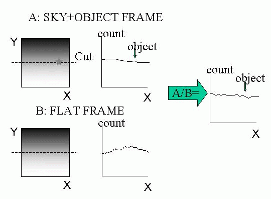
What is 'chop and nod' ?
In the mid-infrared, 'chop and nod' technique is normally used to cancel the very high background radiation. Nod is beam switching by changing the telescope direction a little. Chop is tilting the telescope secondary with a little angle at a telescope position. Chop is done by around 0.1 to a few Hz, and nod is done more slowly (0.03Hz or slower).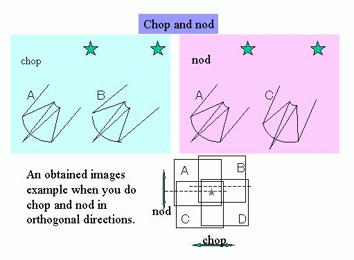
By 'chop and nod', one take images where object is imaged on a bit different positions of the frames. For the obtained data, you first cancel the background radiation by subtracting the blank sky data in the offset beam of the chopping. This corresponding to cancelling fast varing conponents of the background emission. Then remaining residual patterns, which is caused by using different parts of the optics, is removed by make subtraction between frame sets of different nod positions.
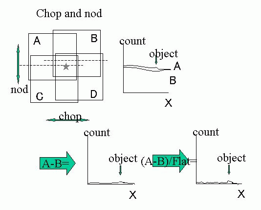
In this method, one don't devide the high sky frames by low-accurate flat frames. One subtract the sky emission by using close sky emission which seems to be almost the same brightness. After this subtraction counts for pixels become around zero. Devision of near zero frame by low-accurate flat frames do not make large artificial fluctuations this time. It becomes easy to detect objects. Nod subtraction is done to cancel artificial structures generated by using different parts of the optics. It is not required when the object brightness (brightness you want to detect) is high enough and then nod method can be omitted.